Frigidaire FGGC3065KW Installation Instructions (All Languages) - Page 7
Install Pressure Regulator
 |
UPC - 057112102702
View all Frigidaire FGGC3065KW manuals
Add to My Manuals
Save this manual to your list of manuals |
Page 7 highlights
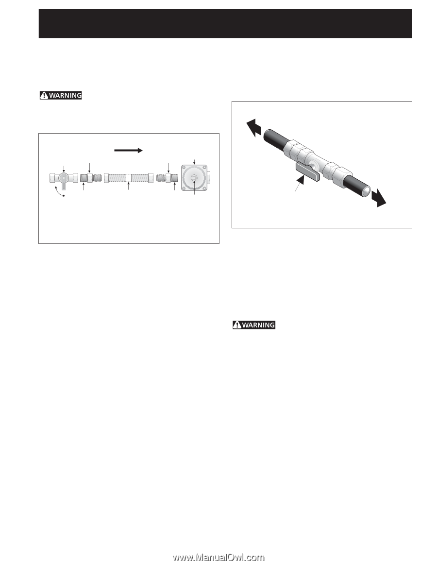
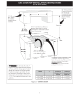
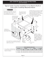
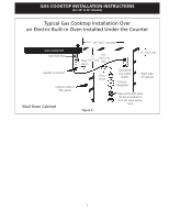
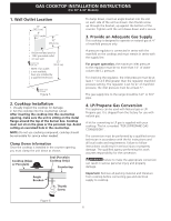
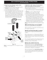
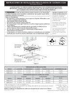
GAS COOKTOP INSTALLATION INSTRUCTIONS (For 30" & 36" Models) 5. Install Pressure Regulator Install the pressure regulator with the arrow on the regulator pointing up toward the unit in a position where you can reach the access cap. Do not make the connection too tight. The regulator is die cast. Overtightening may crack the regulator resulting in a gas leak and possible fire or explosion. The supply line must be equipped with an approved manual shutoff valve. This valve should be located in the same room as the cooktop and should be in a location that allows ease of opening and closing. Do not block access to the shutoff valve. The valve is for turning on or shutting off gas to the appliance. to appliance Manual Shutoff Valve Flare Union GAS FLOW Pressure Flare Regulator Union On Nipple Off Flexible Connector Nipple Access Cap All connections must be wrench-tightened Figure 7 Assemble the flexible connector from the gas supply pipe to the pressure regulator in the following order: 1. manual shutoff valve 2. 1/2" (1.3 cm) nipple 3. 1/2" (1.3 cm) flare union adapter 4. flexible connector 5. 1/2" (1.3 cm) flare union adapter 6. 1/2" (1.3 cm) nipple 7. pressure regulator Use pipe-joint compound made for use with Natural and LP/Propane gas to seal all gas connections. If flexible connectors are used, be certain connectors are not kinked. Shutoff Valve Open position Figure 8 to gas supply line Once regulator is in place, open the shutoff valve in the gas supply line. Wait a few minutes for gas to move through the gas line. Check for leaks. After connecting the cooktop to the gas supply, check the system for leaks with a manometer. If a manometer is not available, turn on the gas supply and use a liquid leak detector (or soap and water) at all joints and connections to check for leaks. Do not use a flame to check for leaks from gas connections. Checking for leaks with a flame may result in a fire or explosion. Tighten all connections if necessary to prevent gas leakage in the cooktop or supply line. Check alignment of control knob valves after connecting the cooktop to the gas supply to be sure the cooktop manifold pipe has not moved. A misalignment could cause the valve stems to rub on the control panel, resulting in a gas leak at the valve. Disconnect this cooktop and its individual manual shutoff valve from the gas supply piping system during any pressure testing of that system at test pressures greater than 1/2 psig (3.5 kPa or 14"water column). Isolate the cooktop from the gas supply piping system by closing its individual manual shutoff valve during any pressure testing of the gas supply piping system at test pressures equal to or less than 1/2 psig (3.5 kPa or 14" water column). 7
-
 1
1 -
 2
2 -
 3
3 -
 4
4 -
 5
5 -
 6
6 -
 7
7 -
 8
8 -
 9
9 -
 10
10 -
 11
11 -
 12
12 -
13
-
14
-
15
-
16
-
17
-
18
-
19
-
20
-
21
-
22
-
23
-
24
-
25
-
26
-
27
-
28
 |
 |