Frigidaire FGGC3065KW Installation Instructions (All Languages) - Page 9
When All Hookups are Complete, Model and Serial Number Location, Before You Call for Service
 |
UPC - 057112102702
View all Frigidaire FGGC3065KW manuals
Add to My Manuals
Save this manual to your list of manuals |
Page 9 highlights
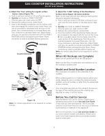
GAS COOKTOP INSTALLATION INSTRUCTIONS (For 30" & 36" Models) 4. Adjust the "low" setting for regular surface burner valves (Figure 10) a. Push in and turn control to LITE until burner ignites. b. Quickly turn knob to LOWEST POSITION. c. If burner goes out, reset control to OFF. d. Remove the surface burner control knob. e. Insert a thin-bladed screwdriver into the hollow valve stem and engage the slotted screw inside. Flame size can be increased or decreased with the turn of the screw. Turn counterclockwise to increase flame size. Turn clockwise to decrease flame size. Adjust flame until you can quickly turn knob from LITE to LOWEST POSITION without extinguishing the flame. Flame should be as small as possible without going out. Clockwise Counterclockwise A Hollow Valve Stem B Regular Burner Valve Dual Burner Valve Figure 10 Note: Air mixture adjustment is not required on surface burners. 5. Adjust the "LOW" Setting of the Dual Burner Surface Valve (Figure 10) (some models): Note: On the dual valve the low setting of each portion should be adjusted individually. a. Push in and turn knob to LITE then continue to turn until only the inner portion of the dual burner stays on. b. Quickly turn knob to LOWEST POSITION. c. If burner goes out, reset control to OFF. d. Remove the surface burner control knob. e. The inner portion of the dual burner flame size can be increased or decreased with the turn of the screw B. Use screw A to adjust the low flame size of the outer portion of the dual burner. Turn the screw counterclockwise to increase flame size. Turn the screw clockwise to decrease flame size. Adjust flame until you can quickly turn knob from HIGH to LOWEST POSITION without extinguishing the flame. Flame should be as small as possible without going out. Note: Air mixture adjustment is not required on surface burners. When All Hookups are Complete Make sure all controls are left in the OFF position. Make sure the flow of combustion and ventilation air to the cooktop is unobstructed. Model and Serial Number Location The serial plate is located on the underside of the cooktop. When ordering parts for or making inquires about your range, always be sure to include the model and serial numbers and a lot number or letter from the serial plate of your cooktop. Your serial plate also tells you the rating of the burners, the type of fuel and the pressure the cooktop was adjusted for when it left the factory. Before You Call for Service Read the Before You Call for Service Checklist and operating instructions in your Use and Care Guide. It may save you time and expense. The list includes common occurrences that are not the result of defective workmanship or materials in this appliance. Refer to the warranty in your Use and Care Guide for our service phone number and address. Please call or write if you have inquiries about your product and/or need to order parts. 9
-
 1
1 -
2
-
3
-
 4
4 -
 5
5 -
 6
6 -
 7
7 -
 8
8 -
 9
9 -
 10
10 -
 11
11 -
 12
12 -
 13
13 -
 14
14 -
15
-
16
-
17
-
18
-
19
-
20
-
21
-
22
-
23
-
24
-
25
-
26
-
27
-
28
 |
 |
