GE AJCS12DCC Owners Manual - Page 9
Care and Cleaning, Safety Instructions
 |
View all GE AJCS12DCC manuals
Add to My Manuals
Save this manual to your list of manuals |
Page 9 highlights
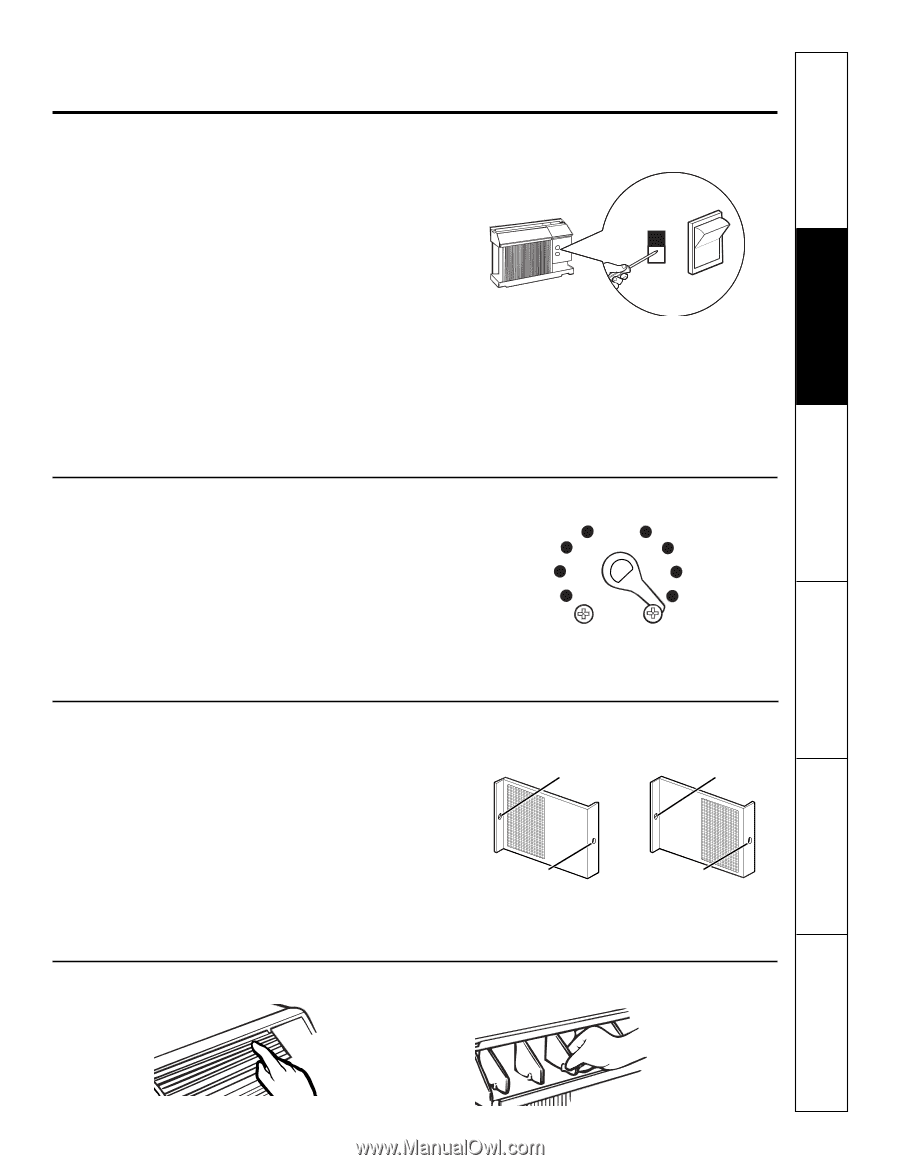
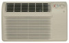
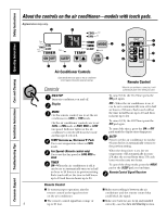
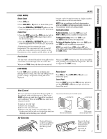
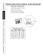
Safety Instructions Operating Instructions Care and Cleaning Installation Instructions Troubleshooting Tips Consumer Support Fan Switch To reach the fan switch(es) remove the front grille. On Heat/Cool and Heat Pump models, the fan switch levers are located in holes accessed through the control box. The top switch is for COOL settings and the bottom switch is for HEAT settings. Use a small screwdriver to change the setting. The unit is shipped from the factory set in the CONT setting for COOL and in the CYCLE setting for HEAT. Cool only models have a rocker switch on the front of the control box. When set at CYCLE (down) the fan cycles on and off when cooling. When set at CONT (continuous, up) the fan runs all the time, providing a more balanced temperature. The unit is shipped in the CONT setting. ge.com or (Depending on model) Temperature Limiting Limiting the maximum and minimum settings prevents users from turning the control to the extreme heat or cool positions. The normal range of the temp control is approximately 60°F to 85°F. The control range may be narrowed by the use of the temperature limiting screws located behind the control panel. Limits heat temp Limits cool temp Each position equals approximately 3°F. Vent Control The vent control is located behind the front grille on the right side of the air discharge area. When set at CLOSE, only the air inside the room will be circulated and conditioned. When set at OPEN, some inside air is exhausted outside. To open or close the vent: 1. Remove the front grille. 2. Remove the vent card screw. 3. Remove vent card, turn it over and replace it by locating rear hole in card over locating pin inside air discharge and reattaching screw at front. The unit leaves the factory set at the CLOSE position. Locating hole Locating hole Screw hole OPEN position (Mesh end toward back) Screw hole CLOSE position (Mesh end toward front) Air Direction Horizontal louvers on the front grille let you control the air direction up and down. Remove the front grille to adjust the vertical louvers side-to-side to direct the air left or right. 9
-
 1
1 -
2
-
3
-
 4
4 -
 5
5 -
 6
6 -
 7
7 -
 8
8 -
 9
9 -
 10
10 -
 11
11 -
 12
12 -
 13
13 -
 14
14 -
15
-
16
-
17
-
18
-
19
-
20
-
21
-
22
-
23
-
24
-
25
-
26
-
27
-
28
-
29
-
30
-
31
-
32
-
33
-
34
-
35
-
36
-
37
-
38
-
39
-
40
-
41
-
42
-
43
-
44
-
45
-
46
-
47
-
48
-
49
-
50
-
51
-
52
-
53
-
54
-
55
-
56
-
57
-
58
-
59
-
60
-
61
-
62
-
63
-
64
-
65
-
66
-
67
-
68
-
69
-
70
-
71
-
72
-
73
-
74
-
75
-
76
 |
 |