GE PDW8600NCC Installation Instructions - Page 4
Warning - dishwasher
 |
View all GE PDW8600NCC manuals
Add to My Manuals
Save this manual to your list of manuals |
Page 4 highlights
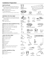
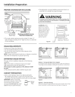
Installation Preparation PREPARE DISHWASHER ENCLOSURE • The dishwasher must be installed so that drain hose is no more than 10' in length for proper drainage. • The rough cabinet opening must be at least 24" deep, 24" wide and approximately 34-1/2" high from floor to underside of the countertop WARNING To reduce the risk of electric shock, fire, or injury to persons, the installer must ensure that the dishwasher is completely enclosed at the time of installation. CLEARANCES: When installed into a corner, allow 2" min. clearance between dishwasher and adjacent cabinet, wall or other appliances. Allow 28-3/8" min. clearance from the front of the dishwasher for door opening. Figure B Figure B DRAIN REQUIREMENTS • Follow local codes and ordinances. • Do not exceed 10' distance to drain. • Do not connect drain lines from other devices to the dishwasher drain hose. NOTE: Air gap must be used if waste tee or disposer connection is less than 18" above floor to prevent siphoning. DETERMINE DRAIN METHOD The type of drain installation depends on the following questions. ■ Do local codes or ordinances require an air gap? ■ Is waste tee less than 18" above floor? If the answer to either question is YES, Method 1 MUST be used. • If the answers are NO, either method may be used. Figure C Meth�od�1�-�A�ir�Ga�p�w�ith Waste Tee or An air gap must be used when required Disposer by�lo�ca�l c�o�de�s�an�d�ordinances. The air gap must be installed according to manufacturer's instructions. CABINET PREPARATION • Drill a 1-1/2" diameter hole in the cabinet wall within the shaded areas shown in Figure A for the drain hose connection. The hole should be smooth with no sharp edges. IMPORTANT: When connecting drain line to disposer, check to be sure that drain plug has been removed. DISHWASHER WILL NOT ���� DRAIN IF PLUG IS LEFT IN PLACE. ��� ��� ���� ���� Figure D Metho�d�2�- D��ra�in�H�os�e Routing When not using an air gap, the drain hose m�us�t �be�r�ou�te�d�to�form a high loop of at least 32" to prevent siphoning. See Step 15 on page 10. 3
-
 1
1 -
 2
2 -
 3
3 -
 4
4 -
 5
5 -
 6
6 -
 7
7 -
 8
8 -
 9
9 -
 10
10 -
11
-
12
-
13
-
14
-
15
-
16
-
17
 |
 |
