GE PDW8600NCC Installation Instructions - Page 7
Installation Instructions, IMPORTANT
 |
View all GE PDW8600NCC manuals
Add to My Manuals
Save this manual to your list of manuals |
Page 7 highlights
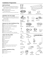
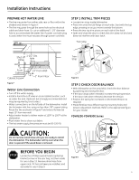
Installation Instructions PDW9200-PDW9900 Series ���� STEP 4 REMOVE TOEKICK • Remove the 2 toekick screws and toekick. Set aside for use in Step 19. Figure K Figure I Tip: If door does not open easily or falls too quickly, check the spring cable routing.�C�h�ec�k�t�ha�t�th�e cable is properly aligned on the pulley. See Figure I. STEP 3 REMOVE WOOD BASE, INSTALL LEVELING LEGS IMPORTANT - Do not kick off wood base! Damage will occur. • Move the dishwasher close to the installation location and lay it on its back. • Remove the four leveling legs on the underside of the wood base with an adjustable wrench or 15/16" socket. • Discard base. STEP 5 REMOVE TOEKICK BRACE Only for PDW9700 series and�PD�W��9�90�0�s�er�ies, otherwise proceed to Step 6. • Remove the 2 toekick brace screws (from the upper set of mounting holes) and toekick brace. Set aside for use in Step 19. Figure L STEP 6 INSTALL POWER CORD Skip this step if dishwasher wi�ll�b�e d��ire�c�t �w�ired or has a factory installed power cord. Use Power Cord Kit WX09X70910, available for purchase from an authorized GE Appliance Dealer. The power cord and connections must comply with the National Electrical Code, Section 422 and/or local codes and ordinances. • Maximum power cord length is 6'. Approx. 1/8" Figure J • Screw leveling legs back into the dishwasher frame, approximately 1/80"5frAom-1fr1a8m3e Qas shown. 6 � Figure M • Connect incoming power cord white (or ribbed) to dishwasher white, black (or smooth) to black and ground to dishwasher • gRreepelancweijruen. UctsioenUbLolixstce�odv�ew�r.ir�Be�en�suu�tsre�ow�f ai�rpepsraorperinaotet size. pinched under the cover.
-
 1
1 -
 2
2 -
 3
3 -
 4
4 -
 5
5 -
 6
6 -
 7
7 -
 8
8 -
 9
9 -
 10
10 -
 11
11 -
 12
12 -
13
-
14
-
15
-
16
-
17
 |
 |
