GE PDW8600NCC Installation Instructions - Page 6
Caution
 |
View all GE PDW8600NCC manuals
Add to My Manuals
Save this manual to your list of manuals |
Page 6 highlights
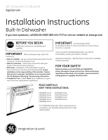
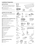
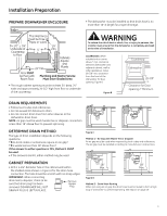
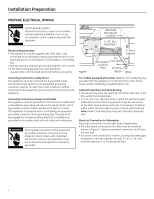
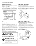
Installation Instructions PREPARE HOT WATER LINE • The line may enter from either side, rear or floor within the shaded area shown in Figure F. • The line may pass through the same hole as the electrical cable and drain hose. Or, cut an additional 1-1/2" diameter hole to accommodate the water line. If power cord with plug is used, water line must not pass through power cord hole. STEP 1 INSTALL TRIM PIECES • Locate trim strips inside dishwasher. • Press trim onto the tub flange on each side. Start with the top edge, pressing on as you move towards the bottom. • Press the two top trim pieces on each side of the latch. • Open and close the door to check that trim does not bind and does not interfere with door latch. Figure F Water Line Con��n�ec��ti�o�n�� • Turn off the water supply. • Install a hand shut-off valve in an accessible location, such as under the sink. (Optional, but strongly recommended and may be required by local codes.) • Water connection is on the left side of the dishwasher. Install the hot water inlet line, using no less than 3/8" copper tubing. Route the line as shown in Figure F and extend forward at least 19" from rear wall. • Adjust water heater to deliver water at 120°F to 150°F at the dishwasher. • Flush water line to clean out debris. • The hot water supply line pressure must be 20-120 PSI. Figure G STEP 2 CHECK DOOR BALANCE • With dishwasher on the wood skid, check the door balance by opening and closing the door. • If the door drops when released, increase the spring tension. If the door rises when released, decrease the tension. • Position the spring for increased or decreased tension as required. • Model families have different spring mounting holes and tension adjustment methods. Refer to the appropriate figure for your model. PDW8200-PDW8900 Series CAUTION: Do not remove wood base until you are ready to install the dishwasher. The dishwasher will tip over when the door is opened if the wood base is removed. STOP BEFORE YOU BEGIN Locate the 2 Phillips special head countertop bracket screws in the user bag. Set them aside for use in Step 13. Remove drain hose from upper rack, if it has not been pre-installed, and set aside for use in Step 9. Figure H 5
-
 1
1 -
 2
2 -
 3
3 -
 4
4 -
 5
5 -
 6
6 -
 7
7 -
 8
8 -
 9
9 -
 10
10 -
 11
11 -
 12
12 -
13
-
14
-
15
-
16
-
17
 |
 |
