GE SG50T12TVT Use and Care Manual - Page 17
Wiring
 |
View all GE SG50T12TVT manuals
Add to My Manuals
Save this manual to your list of manuals |
Page 17 highlights
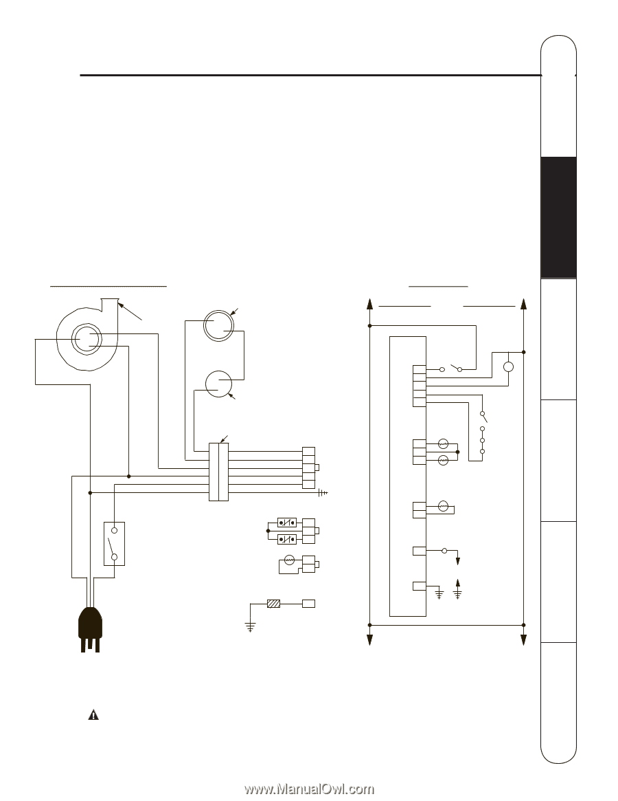
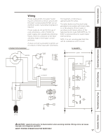
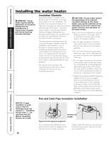
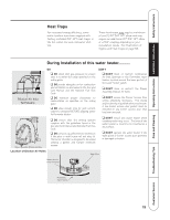
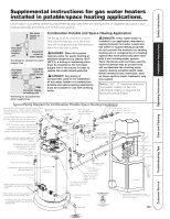
Operating Instructions Installation Instructions Safety Instructions Wiring If local codes permit, the water heater may be connected to electric service with the power cord provided (DO NOT use an extension cord). A grounding receptacle is required. If local codes do not permit the use of cord connections, a 120 V, 50/60 Hz power supply, with suitable disconnecting means, must be connected to the black and white leads in the heater control enclosure. A knock-out hole is provided to permit use of conduit or metal-clad cable connectors. CONNECTION DIAGRAM INDUCER PRESSURE SWITCH BK = BLACK BL = BLUE G = GREEN R = RED W = WHITE Y = YELLOW TEMPERATURE SWITCH The maximum current draw is approximately 5.0 amps. The water heater must be electrically grounded in accordance with local codes, or, in the absence of local codes, in accordance with latest edition of the National Electric Code ANSI/NFPA No. 70. Refer to pictorial below for water heater internal wiring. NOTE: It is not recommended that this unit be installed on a GFCI circuit. SCHEMATIC H N < 120 VAC > P1 1 MOT 2 3 4 5 PS 120 NEUT GROUND 120 VAC 3 x 2 CONNECTOR BL 5 R4 Y3 W2 BK 1 G TS1 BK 1 2 BK 3 TS2 W1 FV 2 W WV 4460E CONTROL P3 TS1 1 TS 2 3 TS2 P2 FV 1 2 E1 1 PILOT ELECTRODE GND ASSY G NH 1 SPARK H 120 N Care and Cleaning Troubleshooting Tips Customer Service CAUTION! Label all wires prior to disconnection when servicing controls. Wiring errors can cause improper and dangerous operation. VERIFY PROPER OPERATION AFTER SERVICING! 17
-
 1
1 -
2
-
3
-
4
-
5
-
6
-
7
-
8
-
9
-
10
-
11
-
 12
12 -
 13
13 -
 14
14 -
 15
15 -
 16
16 -
 17
17 -
 18
18 -
 19
19 -
 20
20 -
 21
21 -
 22
22 -
23
-
24
-
25
-
26
-
27
-
28
-
29
-
30
-
31
-
32
-
33
-
34
-
35
-
36
 |
 |