Gigabyte B650I AORUS ULTRA User Manual - Page 19
Internal Connectors, ATX_12V_2X4
 |
View all Gigabyte B650I AORUS ULTRA manuals
Add to My Manuals
Save this manual to your list of manuals |
Page 19 highlights
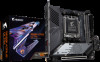
2-8 Internal Connectors 1 3 2 13 17 5 16 15 8 11 12 18 GC-B650I BTB PLUG GC-B650I FRONT CARD 6 10 8 15 7 14 8 9 4 1) ATX_12V_2X4 2) ATX 3) CPU_FAN 4) SYS_FAN1 (Note 1) 5) CPU_OPT 6) LED_C (Note 1) 7) D_LED (Note 2) 8) M2B_CPU (Note 2)/M2A_CPU (Note 3)/M2C_SB (Note 4) 9) SATA3 0/1/2/3 (Note 1) 10) F_PANEL (Note 1) 11) F_AUDIO 12) F_U320G 13) F_U32 14) F_USB (Note 2) 15) RST_SW (Note 2)/RST 16) PW_BT 17) BAT 18) CLR_CMOS (Note 1) The connector is on the front of GC-B650I FRONT CARD. (Note 2) The connector is on the front of GC-B650I BTB PLUG. (Note 3) The connector is on the back of GC-B650I BTB PLUG. (Note 4) The connector is on the back of the motherboard. Read the following guidelines before connecting external devices: •• First make sure your devices are compliant with the connectors you wish to connect. •• Before installing the devices, be sure to turn off the devices and your computer. Unplug the power cord from the power outlet to prevent damage to the devices. •• After installing the device and before turning on the computer, make sure the device cable has been securely attached to the connector on the motherboard. - 19 -
-
 1
1 -
2
-
3
-
4
-
5
-
6
-
7
-
8
-
9
-
10
-
11
-
12
-
13
-
 14
14 -
 15
15 -
 16
16 -
 17
17 -
 18
18 -
 19
19 -
 20
20 -
 21
21 -
 22
22 -
 23
23 -
 24
24 -
25
-
26
-
27
-
28
-
29
-
30
-
31
-
32
-
33
-
34
-
35
-
36
-
37
-
38
 |
 |
