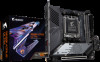
Gigabyte B650I AORUS ULTRA User Manual - Page 27
F_U32 USB 3.2 Gen 1 Header, F_USB, USB 2.0/1.1 Header, Prior to installing the USB bracket
 |
View all Gigabyte B650I AORUS ULTRA manuals
Add to My Manuals
Save this manual to your list of manuals |
Page 27 highlights
13) F_U32 (USBF_3U.S2B3G0 en 1 Header) F_ U F_ The header conforms to USB 3.2 Gen 1 and USB 2.0 specification and can provide two USB ports. For purchasing the optional 3.5" front panel that provides two USB 3.2 Gen 1 ports, please contact the local dealer. Pin No. Definition Pin No. Definition 20 1 1 VBUS 2 SSRX1- 11 D2+ 12 D2- 3 SSRX1+ 4 GND 5B_ SSTX1- G.1Q3BOFMGND 14 SSTXB2S+S 15 SSTX2- 6 SSTX1+ 16 GND 1 11 10 7 GND 17 SSRX2+ _S 8 D1- 18 SSRX2- 9 D1+ 19 VBUS 10 NC 20 No Pin S 1 23 1 1 23 1 1 23 1 DEBUG PORT 1 23 14) F_USB (Note 2) (USB 2.0/1.1 Header) S Connect one end of the front USB header extension cable to this header and the other ends to two USB brackets. The header conforms to USB 2.0/1.1 specification. Each USB header can provide two USB ports via an optional USB bracket. For purchasing the optional USB bracket, please contact the local dealer. S_ S3 9 10 Front USB header extension cable Pin No. Definition 1 Power (5V) 2 Power (5V) 1 B S S2 S 3 4 USB DXUSB DY- U 5 USB DX+ 6 USB DY+ 7 GND 8 GND S F 9 No Pin _ 10 NC Prior to installing the USB bracket, be sure to turn off your computer and unplug the power cord from the power outlet to prevent damage to the USB bracketB._ S _S _ (Note 2) The connector is on the front of GC-B650I BTB PLUG. S_ - 27 -
-
 1
1 -
2
-
3
-
4
-
5
-
6
-
7
-
8
-
9
-
10
-
11
-
12
-
13
-
14
-
15
-
16
-
17
-
18
-
19
-
20
-
21
-
 22
22 -
 23
23 -
 24
24 -
 25
25 -
 26
26 -
 27
27 -
 28
28 -
 29
29 -
 30
30 -
 31
31 -
 32
32 -
33
-
34
-
35
-
36
-
37
-
38
 |
 |
