Gigabyte GA-K8VM800M User Manual
Gigabyte GA-K8VM800M Manual
 |
View all Gigabyte GA-K8VM800M manuals
Add to My Manuals
Save this manual to your list of manuals |
Gigabyte GA-K8VM800M manual content summary:
- Gigabyte GA-K8VM800M | User Manual - Page 1
GA-K8VM800M AMD Socket 754 Processor Motherboard User's Manual Rev. 1003 12ME-K8VM800M-1003 Copyright © 2005 GIGABYTE TECHNOLOGY CO., LTD Copyright by GIGA-BYTE TECHNOLOGY CO., LTD. ("GBT"). No part of this manual may be reproduced or transmitted in any from without the expressed, written permission - Gigabyte GA-K8VM800M | User Manual - Page 2
Mother Board GA-K8VM800M Apr. 14, 2004 - Gigabyte GA-K8VM800M | User Manual - Page 3
Motherboard GA-K8VM800M Apr. 14, 2004 - Gigabyte GA-K8VM800M | User Manual - Page 4
/8X (1.5V) notch" (show below), please make sure your AGP card is AGP 4X/8X. AGP 4X/8X notch Caution: AGP 2X card is not supported by VIA K8M800. You might experience system unable to boot up normally. Please insert an AGP 4X/8X card. GA-K8VM800M Motherboard - 4 - - Gigabyte GA-K8VM800M | User Manual - Page 5
. 5. Ensure that the ATX power supply is switched off before you plug in or remove the ATX power connector on the motherboard. Installing the motherboard to the chassis... If the motherboard has mounting holes, but they don't line up with the holes on the base and there are no slots to attach the - Gigabyte GA-K8VM800M | User Manual - Page 6
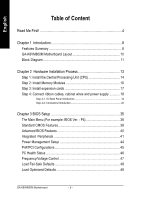
GA-K8VM800M Motherboard Layout 10 Block Diagram 11 Chapter 2 Hardware Installation Process 13 Step 1: Install the Central Processing Unit (CPU 14 Step 2: Install Memory Chapter 3 BIOS Setup 35 The Main Menu (For example: BIOS Ver. : F6 36 Standard CMOS Features 38 Advanced BIOS Features 40 - Gigabyte GA-K8VM800M | User Manual - Page 7
50 Exit Without Saving 50 Chapter 4 Technical Reference 53 @BIOS™ Introduction 53 Flash BIOS Method Introduction 54 2-/4-/6-Channel Audio Function Introduction 65 Jack-Sensing Introduction 71 Xpress Recovery Introduction 73 Serial ATA RAID BIOS Utility Introduction 76 Chapter 5 Appendix 83 - Gigabyte GA-K8VM800M | User Manual - Page 8
VGA y On-Board LAN y y On-Board Sound y y y y y y On-Board SATA RAID y y y y I/O Control y Socket 754 for AMD AlthlonTM 64 processor (K8) 128K L1& 256K / 512K / 1M L2 cache on die , 800MHz FSB Support core frequencies in excess of 1.6 GHz(2800+) and faster Northbridge:VIA K8M800 - Gigabyte GA-K8VM800M | User Manual - Page 9
BIOS Additional Features Overclocking Form Factor y CPU/System fan revolution detect y CPU temperature detect y System voltage detect y CPU/System fan fail warning y Licensed AWARD BIOS y Supports Q-Flash y Supports Thermal Shutdown function y Supports @BIOS y Supports EasyTune y Over Clock (CPU - Gigabyte GA-K8VM800M | User Manual - Page 10
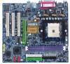
English GA-K8VM800M Motherboard Layout MS / KB SOCKET 754 CPU_FAN R_USB ATX FDD COMA LPT GA-K8VM800M DDR1 VGA USB ATX_12V LAN F_AUDIO AUDIO SUR_CEN VIA K8M800 AGP IT8705F BIOS CODEC CD_IN IR PCI1 PCI2 RTL8100C SPDIF_IO GAME PCI3 COMB INFO_LINK DDR2 IDE2 IDE1 VIA VT8237 - Gigabyte GA-K8VM800M | User Manual - Page 11
AGPCLK (66MHz) VGA Port 3 PCI LAN RJ45 RTL8100C AMD AlthlonTM 64 processor (K8) CPUCLK+/- (200MHz) H.T. Bus 800MHz VIA K8M800 DDR RAM 400/333/266/200MHz 33 MHz 14.318 MHz BIOS VIA VT8237 LPC BUS IT8705F IR Game Port Floppy LPT Port AC97 Link PCICLK (33MHz) 2 Serial ATA Audio 8 USB - Gigabyte GA-K8VM800M | User Manual - Page 12
English GA-K8VM800M Motherboard - 12 - - Gigabyte GA-K8VM800M | User Manual - Page 13
Process To set up your computer, you must complete the following steps: Step 1 - Install the Central Processing Unit (CPU) Step 2 - Install memory modules Step 3 - Install expansion cards Step 4 - Install I/O Peripherals Cables Step 4 Step 1 Step 2 Step 4 Step 3 Step 4 Congratulations! You - Gigabyte GA-K8VM800M | User Manual - Page 14
CPU type is supported by the motherboard. 2. The processor will overheat without the heatsink and/or fan, resulting in permanent irreparable damage. 3. If you do not match the CPU socket Pin 1 and CPU specific bus frequencies properly will depend on your hardware configurations, including CPU, Memory - Gigabyte GA-K8VM800M | User Manual - Page 15
you might pull the processor out of the CPU socket alone with the cooling fan, and might damage the processor. Align the heatsink assembly with the support frame mating with the backer plate standoffs as wires to the header on the motherboard as shown in Figure 6. Figure 6. Connecting the - Gigabyte GA-K8VM800M | User Manual - Page 16
. The BIOS will automatically detects memory type and size. To install the memory module, just push it vertically into the DIMM socket. The DIMM module can only fit in one direction due to the notch. Memory size can vary between sockets. Notch DDR GA-K8VM800M Motherboard 1. The DIMM socket has - Gigabyte GA-K8VM800M | User Manual - Page 17
the screw to secure the slot bracket of the expansion card. 6. Replace your computer's chassis cover. 7. Power on the computer, if necessary, setup BIOS utility of expansion card from BIOS. 8. Install related driver from the operating system. AGP Card Please carefully pull out the small white - Gigabyte GA-K8VM800M | User Manual - Page 18
sure your OS supports USB controller. If your OS does not support USB controller, please contact OS vendor for possible patch or driver upgrade. For more information please contact your OS or device (s) vendors. LAN connector is fast Ethernet with 10/100 Mbps speed. GA-K8VM800M Motherboard - 18 - - Gigabyte GA-K8VM800M | User Manual - Page 19
and VGA Port (LPT/COMA/VGA) This connector supports 1 standard COM port, Parallel Port (25 pin Female) 1 Parallel port and 1 VGA port. Serial Port (9 pin Male) VGA VGA Port (15 pin Female) Audio Connectors Line In Line Out MIC In After install onboard audio driver, you may connect speaker to - Gigabyte GA-K8VM800M | User Manual - Page 20
8) PWR_LED 9) F_PANEL 10) F_AUDIO 11) SUR_CEN 12) SPDIF_IO 13) CD_IN 14) F_USB1 / F_USB2 15) IR 16) GAME 17) INFO_LINK 18) COMB 19) CLR_CMOS 20) BAT GA-K8VM800M Motherboard - 20 - - Gigabyte GA-K8VM800M | User Manual - Page 21
(+12V Power Connector) This connector (ATX_12V) supplies the CPU operation voltage (Vcore). If this "ATX_12V connector" is power supply unit after ATX power cable and other related devices are firmly connected to the motherboard. Pin No. Definition 1 3.3V 2 3.3V 3 GND 11 1 4 VCC 5 GND - Gigabyte GA-K8VM800M | User Manual - Page 22
note, a proper installation of the CPU cooler is essential to prevent the CPU from running under abnormal condition or damaged by overheating. The CPU fan connector supports Max. current up to 600 mA. temperature. Pin No. Definition 1 GND 1 2 +12V 3 Sense GA-K8VM800M Motherboard - 22 - - Gigabyte GA-K8VM800M | User Manual - Page 23
English 5) FDD (Floppy Connector) Please connect the floppy drive ribbon cables to FDD. It supports 360K, 1.2M, 720K, 1.44M and 2.88M bytes floppy disk types. The red stripe of the ribbon cable must be the same side with the Pin1. - Gigabyte GA-K8VM800M | User Manual - Page 24
connect the Serial ATA device to this connector. If you wish to use RAID function, please use it in unity with BIOS and install the correct driver to have proper operation. Pin No. Definition 1 GND 2 TXP 1 color. 1 Pin No. Definition 1 MPD+ 2 MPD- 3 MPD- GA-K8VM800M Motherboard - 24 - - Gigabyte GA-K8VM800M | User Manual - Page 25
English 9) F_PANEL (2 x 10 pins Connector) Please connect the power LED, PC speaker, reset switch and power switch etc. of your chassis front panel to the F_PANEL connector according to the pin assignment below. Speaker Connector Power Switch Message LED/ Power/ Sleep LED 20 19 SPEAK- SPEAK+ - Gigabyte GA-K8VM800M | User Manual - Page 26
Return R NC No Pin FrontAudio (L) Rear Audio (L)/ Return L 11) SUR_CEN (Surround Center Connector) Please contact your nearest dealer for optional SUR_CEN cable. Pin No. Definition 1 SUR OUTL 1 2 2 SUR OUTR 5 6 3 GND 4 No Pin 5 CENTER_OUT 6 BASS_OUT GA-K8VM800M Motherboard - 26 - - Gigabyte GA-K8VM800M | User Manual - Page 27
Out Connector) The SPDIF output is capable of providing digital audio to external speakers or compressed AC3 data to an external GND GND 13) CD_IN (CD In Connector) Connect CD-ROM or DVD-ROM audio out to the connector. 1 Pin No. Definition 1 CD-L 2 GND 3 GND 4 CD-R - 27 - Gigabyte GA-K8VM800M | User Manual - Page 28
damage it. For optional IR cable, please contact your local dealer. Pin No. Definition 1 VCC(+5V) 1 2 No Pin 3 IR Data Input 4 GND 5 IR Data Output GA-K8VM800M Motherboard - 28 - - Gigabyte GA-K8VM800M | User Manual - Page 29
English 16) GAME (Game Connector) This connector supports joystick, MIDI keyboard and other relate audio devices. Check the pin assignment while you connect the game cables. Please contact your nearest dealer for optional game cables. Pin No. Definition 1 VCC 2 GRX1_R 2 - Gigabyte GA-K8VM800M | User Manual - Page 30
this jumper. To clear CMOS, temporarily short 1-2 pin. Default doesn't include the "Shunter" to prevent from improper use this jumper. 1 Open: Normal 1 Short: Clear CMOS GA-K8VM800M Motherboard - 30 - - Gigabyte GA-K8VM800M | User Manual - Page 31
+ CAUTION Danger of explosion if battery is incorrectly replaced. Replace only with the same or equivalent type recommended by the manufacturer. Dispose of used batteries according to the manufacturer's instructions. If you want to erase CMOS... 1. Turn OFF the computer and unplug the power cord - Gigabyte GA-K8VM800M | User Manual - Page 32
English GA-K8VM800M Motherboard - 32 - - Gigabyte GA-K8VM800M | User Manual - Page 33
- 33 - Hardware Installation Process English - Gigabyte GA-K8VM800M | User Manual - Page 34
English GA-K8VM800M Motherboard - 34 - - Gigabyte GA-K8VM800M | User Manual - Page 35
BIOS, either Gigabyte's Q-Flash or @BIOS utility can be used. Q-Flash allows the user to quickly and easily update or backup BIOS without entering the operating system. @BIOS is a Windows-based utility that does not require users to boot to DOS before upgrading BIOS but directly download and update - Gigabyte GA-K8VM800M | User Manual - Page 36
z Standard CMOS Features This setup page includes all the items in standard compatible BIOS. z Advanced BIOS Features This setup page includes all the items of Award special enhanced features. z Integrated Peripherals This setup page includes all onboard peripherals. GA-K8VM800M Motherboard - 36 - - Gigabyte GA-K8VM800M | User Manual - Page 37
auto detect Temperature, voltage, fan, speed. z Frequency/Voltage Control This setup page is control CPU's clock and frequency ratio. z Load Fail-SafeDefaults Fail-Safe Defaults indicates the value of the system z Exit Without Saving Abandon all CMOS value changes and exit setup. - 37 - BIOS Setup - Gigabyte GA-K8VM800M | User Manual - Page 38
start up. Manual User can manually input the correct BIOS to automatically detect SATA IDE devices during POST. (Default value) None Select this if no SATA IDE devices are used and the system will skip the automatic detection step and allow for faster system start up. GA-K8VM800M Motherboard - Gigabyte GA-K8VM800M | User Manual - Page 39
capacity. Floppy 3 Mode Support (for Japan Area) memory installed on the motherboard. Extended Memory The BIOS determines how much extended memory is present during the POST. This is the amount of memory located above 1 MB in the CPU's memory address map. Total Memory This item displays the memory - Gigabyte GA-K8VM800M | User Manual - Page 40
Award Software Advanced BIOS Features ` Hard Disk Boot Priority Select boot sequence for onboard(or add-on cards) SCSI, RAID, etc. Use < > or < > to select a device, then by USB-HDD. Legacy LAN Select your boot device priority by Legacy LAN. Disabled Disable this GA-K8VM800M Motherboard - 40 - - Gigabyte GA-K8VM800M | User Manual - Page 41
access On-Chip IDE Channel 0 On-Chip IDE Channel 1 OnChip Serial ATA SATA Mode AC97 Audio USB 1.1 Controller USB 2.0 Controller USB Keyboard Support USB Mouse Support Onboard H/W LAN Onboard LAN Boot ROM Onboard FDC Controller Onboard Serial Port 1 Onboard Serial Port 2 UART Mode Select x UR2 - Gigabyte GA-K8VM800M | User Manual - Page 42
supported. (Default value) Disabled Disable VT8237 Serial ATA supported. SATA Mode RAID IDE Set onboard SATA mode to RAID. (Default value) Set onboard SATA mode to IDE. AC97 Audio Auto Disabled Enable onboard AC'97 audio Disabled Disable onboard Serial port 1. GA-K8VM800M Motherboard - 42 - - Gigabyte GA-K8VM800M | User Manual - Page 43
English Onboard Serial Port 2 Auto BIOS will automatically setup the port 2 address. 3F8/IRQ4 Enable onboard Serial port 2 and address is 3F8/IRQ4. 2F8/IRQ3 Enable onboard (Default value) Midi Port IRQ 5 Set Midi Port IRQ to 5. 10 Set Midi Port IRQ to 10. (Default value) - 43 - BIOS Setup - Gigabyte GA-K8VM800M | User Manual - Page 44
S3(STR) Set ACPI suspend type to S3/STR (Suspend To RAM). USB Device Wake-Up From S3 Disabled Disable this function. (Default if button is pressed less than 4 seconds. AC Back Function Soft-Off Memory Full-On Always in off state when AC back. (Default value) GA-K8VM800M Motherboard - 44 - - Gigabyte GA-K8VM800M | User Manual - Page 45
English Modem Ring On An incoming call via modem can awake the system from any suspend state. Disabled Disable Modem Ring on function. Enabled Enable Modem Ring on function. 14,15 to PCI 2. Auto assign IRQ to PCI 3. (Default value) Set IRQ 3,4,5,7,9,10,11,12,14,15 to PCI 3. - 45 - BIOS Setup - Gigabyte GA-K8VM800M | User Manual - Page 46
speed status automatically. CPU FAN Fail Warning Disabled Fan warning function disable. (Default value) Enabled Fan warning function enable. SYSTEM FAN Fail Warning Disabled Fan warning function disable. (Default value) Enabled Fan warning function enable. GA-K8VM800M Motherboard - 46 - - Gigabyte GA-K8VM800M | User Manual - Page 47
CPU Clock Ratio Default Set K8 CPU Clock Ratio to CPU factory default. (Default value) x4 800Mhz ~ x10 2000Mhz Set K8 CPU Clock Ratio from x4 800Mhz to x10 2000Mhz. CPU Host Clock Control Note: Please note that if your system is overclocked Card when enable this feature. - 47 - BIOS Setup - Gigabyte GA-K8VM800M | User Manual - Page 48
Copyright (C) 1984-2005 Award Software ` Standard CMOS Features ` Advanced BIOS Features ` Integrated Peripherals ` Power Management Setup ` PnP/PCI Configurations field loads the factory defaults for BIOS and Chipset Features which the system automatically detects. GA-K8VM800M Motherboard - 48 - - Gigabyte GA-K8VM800M | User Manual - Page 49
the system will boot and you can enter Setup freely. The BIOS Setup program allows you to specify two separate passwords: SUPERVISOR PASSWORD and only basic items. If you select "System" at "Password Check" in Advance BIOS Features Menu, you will be prompted for the password every time the system is - Gigabyte GA-K8VM800M | User Manual - Page 50
CMOS Setup Utility-Copyright (C) 1984-2005 Award Software ` Standard CMOS Features ` Advanced BIOS Features ` Integrated Peripherals ` Power Management Setup ` PnP/PCI Configurations ` PC Health without saving to RTC CMOS. Type "N" will return to Setup Utility. GA-K8VM800M Motherboard - 50 - - Gigabyte GA-K8VM800M | User Manual - Page 51
- 51 - BIOS Setup English - Gigabyte GA-K8VM800M | User Manual - Page 52
English GA-K8VM800M Motherboard - 52 - - Gigabyte GA-K8VM800M | User Manual - Page 53
motherboard vendors could not just do something right to save your time and effort and save you from the lousy BIOS updating work? Here it comes! Now Gigabyte announces @BIOS -- the first Windows BIOS live update utility. This is a smart BIOS update software. It could help you to download the BIOS - Gigabyte GA-K8VM800M | User Manual - Page 54
first. 1. Download the latest BIOS for your motherboard from Gigabyte's website. 2. Extract the BIOS file downloaded and save the BIOS file (the one with model name.Fxx. For example, 8KNXPU.Fba) to a floppy disk. 3. Reboot your PC and press Del to enter BIOS menu. The BIOS upgrading guides below are - Gigabyte GA-K8VM800M | User Manual - Page 55
English Part One: Updating BIOS with Q-FlashTM Utility on Dual BIOS Motherboards. Some of Gigabyte motherboards are equipped with dual BIOS. In the BIOS menu of the motherboards supporting Q-Flash and Dual BIOS, the Q-Flash utility and Dual BIOS utility are combined in the same screen. This - Gigabyte GA-K8VM800M | User Manual - Page 56
item in the Q-Flash menu and press Enter button. Later, you will see a box pop up showing the BIOS files you previously downloaded to the floppy disk. If you want to save the current BIOS for backup purpose, you can begin Step 1 with "Save Main BIOS to Floppy" item. GA-K8VM800M Motherboard - 56 - - Gigabyte GA-K8VM800M | User Manual - Page 57
flash and press Enter. In this example, we only download one BIOS file to the floppy disk so only one BIOS file, 8KNXPU.Fba, is listed. Please confirm again you have the correct BIOS file for your motherboard. Dual BIOS Utility Boot From Main Bios Main ROM Type/Size SST 49LF003A Backup ROM Type - Gigabyte GA-K8VM800M | User Manual - Page 58
Primary Master : FUJITSU MPE3170AT ED-03-08 Primary Slave : None Secondary Master : CREATIVEDVD-RM DVD1242E BC101 Secondary Slave : None Press DEL to enter SETUP / Dual BIOS / Q-Flash / F9 For Xpress Recovery 09/23/2003-i875P-6A79BG03C-00 GA-K8VM800M Motherboard - 58 - - Gigabyte GA-K8VM800M | User Manual - Page 59
to Load Fail-Safe Defaults item and press Enter to load BIOS Fail-Safe Defaults. Normally the system redetects all devices after BIOS has been upgraded. Therefore, we highly recommend reloading the BIOS defaults after BIOS has been upgraded. CMOS Setup Utility-Copyright (C) 1984-2003 Award Software - Gigabyte GA-K8VM800M | User Manual - Page 60
Two: Updating BIOS with Q-FlashTM Utility on Single-BIOS Motherboards. This part guides users of single-BIOS motherboards how to update BIOS using the Q-Flash™ utility. Entering the Q-FlashTM utility: Step1: To use the Q-Flash utility, you must press Del in the boot screen to enter BIOS menu. CMOS - Gigabyte GA-K8VM800M | User Manual - Page 61
this example, we only download one BIOS file to the floppy disk so only one BIOS file, 8GE800.F4, is listed. Please confirm again you have the correct BIOS file for your motherboard. Q-Flash Utility V1.30 Flash Type/Size SST 49LF003A 256K Keep DMI Data Enable Update BIOS from Floppy 8GE800.F4 - Gigabyte GA-K8VM800M | User Manual - Page 62
03/18/2003-I845GE-6A69YG01C-00 6. Press Del to enter BIOS menu after system reboots and "Load BIOS Fail-Safe Defaults". See how to Load BIOS Fail-Safe Defaults, please kindly refer to Step 6 to 7 in Part One. Congratulation!! You have updated BIOS successfully!! GA-K8VM800M Motherboard - 62 - - Gigabyte GA-K8VM800M | User Manual - Page 63
not click "Internet Update" icon b. Click "Update New BIOS" c. Please select "All Files" in dialog box while opening the old file. d. Please search for BIOS unzip file, downloading from internet or any other methods. (such as: K8VM800M.D8). e. Complete update process following the instruction. - 63 - Gigabyte GA-K8VM800M | User Manual - Page 64
system won't boot. c . In method I, if the BIOS file you need cannot be found in @BIOS™ server, please go onto Gigabyte's web site for downloading and updating it according to method II. d. Please note that any interruption during updating will cause system unbooted. GA-K8VM800M Motherboard - 64 - - Gigabyte GA-K8VM800M | User Manual - Page 65
1: Connect the stereo speakers or earphone to "Line Out". STEP 2 : After installation of the audio driver, you'll find an icon on the taskbar's status area. Click the audio icon "Sound Effect" from the windows tray at the bottom of the screen. Line Out STEP 3: Select "Speaker Configuration", and - Gigabyte GA-K8VM800M | User Manual - Page 66
installation of the audio driver, you'll find an icon on the taskbar's status area. Click the audio icon "Sound Effect" from the windows tray at the the sound would be performed as stereo mode (2 channels output). Please select the other settings for 4 channels output. GA-K8VM800M Motherboard - - Gigabyte GA-K8VM800M | User Manual - Page 67
the Center/Subwoofer channels to "MIC In". MIC In Line Out STEP 2 : After installation of the audio driver, you'll find an icon on the taskbar's status area. Click the audio icon "Sound Effect" from the windows tray at the bottom of the screen. Line In STEP 3 : Select "Speaker Configuration", and - Gigabyte GA-K8VM800M | User Manual - Page 68
English Advanced 6 Channel Analog Audio Output Mode (using Audio Combo Kit,Optional Device): (Audio Combo Kit provides SPDIF output , Line In and MIC at the same time. "SURROUND-KIT" is included in the GIGABYTE unique "Audio Combo Kit" as picture. STEP 1 : Insert the "SURROUND-KIT" in the back of - Gigabyte GA-K8VM800M | User Manual - Page 69
", the rear channels to SURROUND-KIT's REAR R/L, and the Center/Subwoofer channels to SURROUND-KIT's SUB CENTER. STEP 4 : Click the audio icon "Sound Effect" from the windows tray at the bottom of the screen. STEP 5 : Select "Speaker Configuration", and choose the "6 channel for 5.1 speakers out put - Gigabyte GA-K8VM800M | User Manual - Page 70
Output Device (Optional Device) A "SPDIF output" device is available on the motherboard. Cable with rear bracket is provided and could link to the "SPDIF , and fix it with screw. 2. Connect SPDIF device to the motherboard. 3. Connect SPDIF to the SPDIF decoder. GA-K8VM800M Motherboard - 70 - - Gigabyte GA-K8VM800M | User Manual - Page 71
DirectX8.1 before to enable Jack-Sensing support for Windows 98/98SE/2000 /ME. Jack-Sensing includes 2 parts: AUTO and MANUAL. Following is an example for 2 channels (Windows XP): Introduction of audio connectors You may connect CDROM, Walkman or others audio input devices to Line In jack, speakers - Gigabyte GA-K8VM800M | User Manual - Page 72
English If you set wrong with the connectors, the warning message will come out as right picture. Manual setting: If the device picture shows different from what you set, please press "Manual Selecion" to set. GA-K8VM800M Motherboard - 72 - - Gigabyte GA-K8VM800M | User Manual - Page 73
be used with an IDE hard disk supporting HPA 5. The first partition must be BIOS menu, select "Advanced BIOS Feature" and set to boot from CD-ROM. Insert the provided driver CD into your CD drive, then save and exit the BIOS V1.0 (C) Copy Right 2003. GIGABYTE Technology CO. , Ltd. 1. Execute - Gigabyte GA-K8VM800M | User Manual - Page 74
F9 during powering on the computer. Award Modular BIOS v6.00PG, An Energy Star Al ly Copyright (C) 1984-2002, Award Software, Inc. Intel 865PE AGPSet BIOS for 8IPE1000MT F1 Check System Health OK . OS and all required driver and software installations are complete. GA-K8VM800M Motherboard - 74 - - Gigabyte GA-K8VM800M | User Manual - Page 75
Esc to Exit The backup utility will automatically scan your system and back up data as a backup image in your hard drive. Not all systems support access to Xpress Recovery by pressing the F9 key during computer power on. If this is the case, please use the boot from CD-ROM - Gigabyte GA-K8VM800M | User Manual - Page 76
English Serial ATA BIOS Setting Utility Introduction RAID Levels RAID (Redundant Array . The RAID levels which the VIA VT8237 southbridge chipset supports are RAID 0, 1, and JBOD. RAID 0 (Striping) RAID 0 reads not really a RAID and does not support fault tolerance. GA-K8VM800M Motherboard - 76 - - Gigabyte GA-K8VM800M | User Manual - Page 77
or SATA. 3) Enter the motherboard BIOS and locate RAID setup (Please refer to the section on Integrated Peripherals). 4) Enter RAID setup in the BIOS and select the RAID type (For instance, enter to select VIA RAID). 5) Complete driver installation. 6) Complete RAID utility installation. More - Gigabyte GA-K8VM800M | User Manual - Page 78
to VIA IDE controller F1 : View Array/disk Status K, L : Move to next item Enter : Confirm the selection ESC : Exit Channel Serial_Ch0 Master Serial_Ch1 Master Driver Name ST380013AS ST9120023AS Array Name Mode SATA SATA Size(GB) 74.53 111.79 Status Hdd Hdd GA-K8VM800M Motherboard - 78 - Gigabyte GA-K8VM800M | User Manual - Page 79
Master Driver Name ST380013AS ST9120023AS Array Name Mode SATA SATA Size(GB) 74.53 111.79 Status Stripe0 Stripe1 4. If user selects a RAID 0 4KB to 64KB. VIA Technologies,Inc. VIA VT8237 Serial ATA BIOS Setting Utility V1.20 X Auto Setup For Performance 4K X Array Mode RAID 0 (Striping8)K X - Gigabyte GA-K8VM800M | User Manual - Page 80
array F1 K, L Enter ESC : View Array/disk Status : Move to next item : Confirm the selection : Exit Channel [*]Serial_Ch0 Master [*]Serial_Ch1 Master Driver Name ST380013AS ST9120023AS Array Name Mode SATA SATA Size(GB) 74.53 111.79 Status Stripe0 Stripe1 GA-K8VM800M Motherboard - 80 - - Gigabyte GA-K8VM800M | User Manual - Page 81
Technologies,Inc. VIA VT8237 Serial ATA BIOS Setting Utility V1.20 X Create Array X Delete Array X Create/Delete Spare X Select Boot Array X Serial Number View Create a RAID array with the hard disks attached to VIA IDE controller F1 : View Array/disk Status K, L : Move to next item Enter - Gigabyte GA-K8VM800M | User Manual - Page 82
installation. (Each time you add a new hard drive to a RAID array, the RAID driver will have to be installed under Windows once for that hard drive. After that, the driver will not have to be installed.) Note: In the menu list, IAA_RAID is Intel ICH5R chipset. GA-K8VM800M Motherboard - 82 - - Gigabyte GA-K8VM800M | User Manual - Page 83
English RCehvaispiotenrH5istAoprypendix Install Drivers Pictures below are shown in Windows XP Insert the driver CD-title that came with your motherboard into your CD-ROM drive, the driver CD-title will auto start and show the installation guide. If not, please double click the CD-ROM device icon - Gigabyte GA-K8VM800M | User Manual - Page 84
up issue in XP. „ Realtek Lan Driver RealTek 10/100 LAN driver „ RealTek AC97 Codec Driver Realtek Audio Driver „ VIA 8237 Serial ATA Driver For VIA 8237 SATA Driver „ VIA USB 2.0 Controller VIA USB 2.0 Host Controller use the inbox driver in Service Pack 1 Please upgrade to Windows XP Service Pack - Gigabyte GA-K8VM800M | User Manual - Page 85
via the network „ EasyTune 4 Powerful utility that integrates the overclocking and hardware monitoring functions „ DMI Viewer Windows based utility which is used to browse the DMI/SMBIOS information of the system „ Face-Wizard New utility for adding BIOS logo „ @BIOS Gigabyte windows flash BIOS - Gigabyte GA-K8VM800M | User Manual - Page 86
English SOFTWARE INFORMATION This page list the contects of softwares and drivers in this CD title. HARDWARE INFORMATION This page lists all device you have for this motherboard. CONTACT US Please see the last page for details. GA-K8VM800M Motherboard - 86 - - Gigabyte GA-K8VM800M | User Manual - Page 87
disk before installing drivers. You also need to go through some rather different steps in the installation process. Therefore, we suggest that you refer to the installation steps in the RAID manual at our website. (Please download it at http://tw.giga-byte.com/support/user_pdf/raid_manual.pdf - Gigabyte GA-K8VM800M | User Manual - Page 88
IDE/ SCSI/ RAID card ? Answer:Please set in the BIOS as follow: 1. Advanced BIOS features-->(SATA)/RAID/SCSI boot order: "SCSI" 2. Advanced BIOS features--> First boot device: "SCSI" Then it depends on the mode(RAID or ATA) that you need to set in RAID/ SCSI BIOS. GA-K8VM800M Motherboard - 88 - - Gigabyte GA-K8VM800M | User Manual - Page 89
trouble during boot up, please follow the troubleshooting procedures. START Turn off the power and unplug the AC power cable, then remove all of the add-on cards and cables from motherboard. Please make sure motherboard & chassis are not short ? No Please make sure all jumper settings (such as CPU - Gigabyte GA-K8VM800M | User Manual - Page 90
your problem, please contact with your local retailer or national distributor for help. Or, you could submit your question to the service mail via Gigabyte website technical support zone (http://www.gigabyte.com.tw). The appropriate response will be provided ASAP. GA-K8VM800M Motherboard - 90 - Gigabyte GA-K8VM800M | User Manual - Page 91
/Lot Number: BIOS version: O.S./A.S.: Hardware Mfs. Model name Size: Configuration CPU Memory Brand Video Card Audio Card HDD CD-ROM / DVD-ROM Modem Network AMR / CNR Keyboard Mouse Power supply Other Device Phone No.: PCB revision: Driver/Utility: Problem Description: - 91 - Gigabyte GA-K8VM800M | User Manual - Page 92
BIOS CPU CMOS CRIMM CNR DMA DMI DIMM DRM DRAM DDR ECP ESCD ECC EMC EPP ESD FDD FSB HDD IDE IRQ Meaning Advanced Configuration and Power Interface Advanced Power Management Accelerated Graphics Port Audio Dual Channel Enhanced Interrupt Request to be continued...... GA-K8VM800M Motherboard - 92 - - Gigabyte GA-K8VM800M | User Manual - Page 93
Acronyms IOAPIC ISA LAN I/O LBA LED Memory Translator Hub Memory Protocol Translator Network Interface Card Operating System Original Equipment Manufacturer PCI A.G.P. Controller Power-On Self Test Peripheral Component Interconnect Rambus in-line Memory Module Special Circumstance Instructions - Gigabyte GA-K8VM800M | User Manual - Page 94
English GA-K8VM800M Motherboard - 94 - - Gigabyte GA-K8VM800M | User Manual - Page 95
- 95 - Memo English - Gigabyte GA-K8VM800M | User Manual - Page 96
via the information in this page all over the world. y Taiwan Gigabyte Technology Co., Ltd. Address: No.6, Bau Chiang Road, Hsin-Tien, Taipei Hsien, Taiwan, R.O.C. Tel: 886 (2) 8912-4888 Fax: 886 (2) 8912-4003 Tech. Support Xian Tel: 86-29-5531943 Fax: 86-29-5539821 GA-K8VM800M Motherboard - 96 -
-
 1
1 -
 2
2 -
 3
3 -
 4
4 -
 5
5 -
 6
6 -
 7
7 -
8
-
9
-
10
-
11
-
12
-
13
-
14
-
15
-
16
-
17
-
18
-
19
-
20
-
21
-
22
-
23
-
24
-
25
-
26
-
27
-
28
-
29
-
30
-
31
-
32
-
33
-
34
-
35
-
36
-
37
-
38
-
39
-
40
-
41
-
42
-
43
-
44
-
45
-
46
-
47
-
48
-
49
-
50
-
51
-
52
-
53
-
54
-
55
-
56
-
57
-
58
-
59
-
60
-
61
-
62
-
63
-
64
-
65
-
66
-
67
-
68
-
69
-
70
-
71
-
72
-
73
-
74
-
75
-
76
-
77
-
78
-
79
-
80
-
81
-
82
-
83
-
84
-
85
-
86
-
87
-
88
-
89
-
90
-
91
-
92
-
93
-
94
-
95
-
96
 |
 |

GA-K8VM800M
User's Manual
AMD Socket 754 Processor Motherboard
Rev. 1003
12ME-K8VM800M-1003
Copyright
© 2005 GIGABYTE TECHNOLOGY CO., LTD
Copyright by
GIGA-BYTE TECHNOLOGY CO., LTD.
("GBT").
No part of this manual may
be reproduced or transmitted in any from
without the expressed, written permission of
GBT
.
Trademarks
Third-party brands and names are the property of their respective owners.
Notice
Please do not remove any labels on motherboard, this may void the warranty of this motherboard.
Due to rapid change in technology, some of the specifications might be out of date before publication of this booklet.
The author assumes no responsibility for any errors or omissions that may appear in this document nor does the author make a
commitment to update the information contained herein.