Gigabyte GA-K8VM800M User Manual - Page 15
Hardware Installation Process - cpu support
 |
View all Gigabyte GA-K8VM800M manuals
Add to My Manuals
Save this manual to your list of manuals |
Page 15 highlights
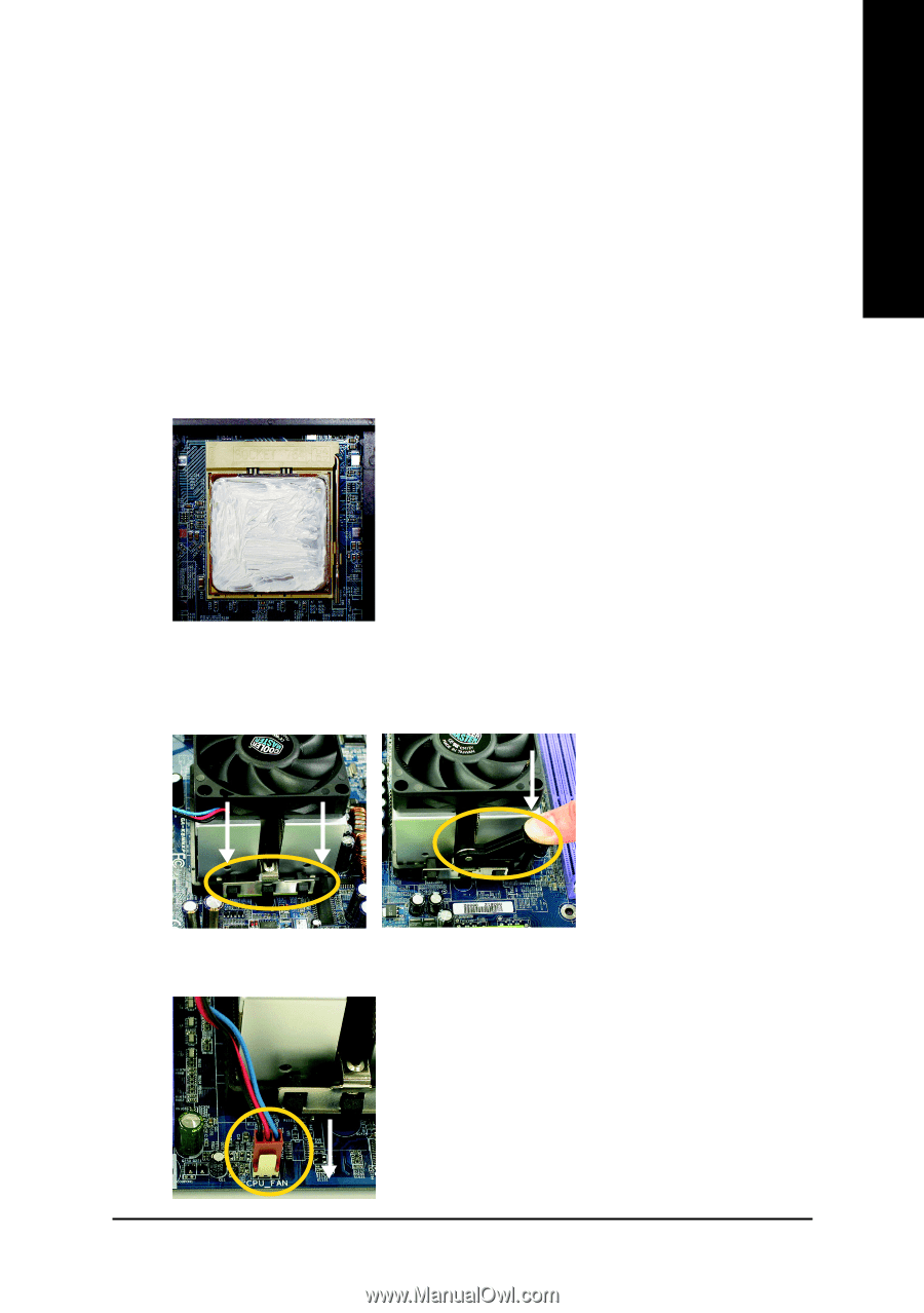
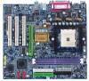
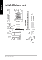
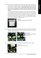
English Step1-2. When the processor is installed in the socket, apply thermal grease to the processor(as shown in Figure 3) prior to installing the heatsink. Phase change materials develop strong adhesive forces between the heatsink and processor. Removing the heatsink under such conditions can cause the processor to be removed from the socket without moving the socket lever to the unlocked position and then damage the processor pins or socket contacts. ** We recommend you to apply the thermal tape to provide better heat conduction between your CPU and heatsink. (The CPU cooling fan might stick to the CPU due to the hardening of the thermal paste. During this condition if you try to remove the cooling fan, you might pull the processor out of the CPU socket alone with the cooling fan, and might damage the processor. To avoid this from happening, we suggest you to either use thermal tape instead of thermal paste, orremove the cooling fan with extreme caution.) Figure 3. Application of thermal grease to the processor. Step 1-3.Once the thermal grease has been applied to the processor, the heatsink can be attached to the processor. Align the heatsink assembly with the support frame mating with the backer plate standoffs as shown in Figure 4 & 5. Figure 4 & 5. Alignment of heatsink assembly with standoffs. Step 1-4. Connect the fan power wires to the header on the motherboard as shown in Figure 6. Figure 6. Connecting the fan power wires. - 15 - Hardware Installation Process
-
 1
1 -
2
-
3
-
4
-
5
-
6
-
7
-
8
-
9
-
 10
10 -
 11
11 -
 12
12 -
 13
13 -
 14
14 -
 15
15 -
 16
16 -
 17
17 -
 18
18 -
 19
19 -
 20
20 -
21
-
22
-
23
-
24
-
25
-
26
-
27
-
28
-
29
-
30
-
31
-
32
-
33
-
34
-
35
-
36
-
37
-
38
-
39
-
40
-
41
-
42
-
43
-
44
-
45
-
46
-
47
-
48
-
49
-
50
-
51
-
52
-
53
-
54
-
55
-
56
-
57
-
58
-
59
-
60
-
61
-
62
-
63
-
64
-
65
-
66
-
67
-
68
-
69
-
70
-
71
-
72
-
73
-
74
-
75
-
76
-
77
-
78
-
79
-
80
-
81
-
82
-
83
-
84
-
85
-
86
-
87
-
88
-
89
-
90
-
91
-
92
-
93
-
94
-
95
-
96
 |
 |