Gigabyte GA-K8VM800M User Manual - Page 14
Step 1: Install the Central Processing Unit CPU - specifications
 |
View all Gigabyte GA-K8VM800M manuals
Add to My Manuals
Save this manual to your list of manuals |
Page 14 highlights
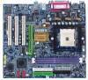
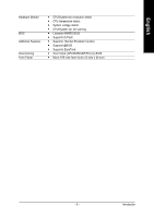
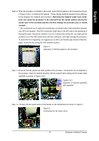
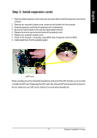
English Step 1: Install the Central Processing Unit (CPU) Before installing the processor and cooling fan, adhere to the following warning: 1. Please make sure the CPU type is supported by the motherboard. 2. The processor will overheat without the heatsink and/or fan, resulting in permanent irreparable damage. 3. If you do not match the CPU socket Pin 1 and CPU cut edge well, it will cause improper installation. Please change the insert orientation. 4. Apply thermal grease between the processor and cooling fan. 5. Never run the processor without the heatsink properly and firmly attached. Permanent damage will result. 6. Please set the CPU host frequency in accordance with your processor's specifications. We don't recommend you to set the system bus frequency over the CPU's specification because these specific bus frequencies are not the standard specifications for CPU, chipset and most of the peripherals. Whether your system can run under these specific bus frequencies properly will depend on your hardware configurations, including CPU, Memory, Cards...etc. The installation of the processor and cooling fan is performed in four main steps: Step1-1. First, check the processor pins to see that none are bent. Move the socket lever to the unlocked position as shown in Figure 1.(90o to the plane of the motherboard) prior to inserting the processor. The pin 1 location is designated on the processor by a copper triangle that matches up to a triangle on the socket as shown in Figure 2. Align the processor to the socket and gently lower it into place. Do not force the processor into the socket. Socket Lever Figure 1. Pull the lever to the 90-degree directly. Figure 2. Pin 1 location on the Socket and Processor. Move the socket lever to the locked position while holding pressure on the center of the processor. GA-K8VM800M Motherboard - 14 -
-
 1
1 -
2
-
3
-
4
-
5
-
6
-
7
-
8
-
 9
9 -
 10
10 -
 11
11 -
 12
12 -
 13
13 -
 14
14 -
 15
15 -
 16
16 -
 17
17 -
 18
18 -
 19
19 -
20
-
21
-
22
-
23
-
24
-
25
-
26
-
27
-
28
-
29
-
30
-
31
-
32
-
33
-
34
-
35
-
36
-
37
-
38
-
39
-
40
-
41
-
42
-
43
-
44
-
45
-
46
-
47
-
48
-
49
-
50
-
51
-
52
-
53
-
54
-
55
-
56
-
57
-
58
-
59
-
60
-
61
-
62
-
63
-
64
-
65
-
66
-
67
-
68
-
69
-
70
-
71
-
72
-
73
-
74
-
75
-
76
-
77
-
78
-
79
-
80
-
81
-
82
-
83
-
84
-
85
-
86
-
87
-
88
-
89
-
90
-
91
-
92
-
93
-
94
-
95
-
96
 |
 |