Gigabyte GA-M61PME-S2 Manual
Gigabyte GA-M61PME-S2 Manual
 |
UPC - 818313005199
View all Gigabyte GA-M61PME-S2 manuals
Add to My Manuals
Save this manual to your list of manuals |
Gigabyte GA-M61PME-S2 manual content summary:
- Gigabyte GA-M61PME-S2 | Manual - Page 1
GA-M61PME-S2 AM2 socket motherboard for AMD AthlonTM 64 FX processor/ AMD AthlonTM 64 X2 Dual-Core processor/ AMD AthlonTM 64 processor/AMD SempronTM processor User's Manual Rev. 2003 12ME-M61PMES2-2003R - Gigabyte GA-M61PME-S2 | Manual - Page 2
Motherboard GA-M61PME-S2 Jan. 16, 2008 Motherboard GA-M61PME-S2 Jan. 16, 2008 - Gigabyte GA-M61PME-S2 | Manual - Page 3
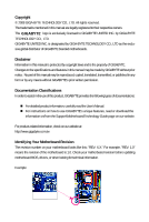
of documentations: For detailed product information, carefully read the User's Manual. For instructions on how to use GIGABYTE's unique features, read or download the information on/from the Support\Motherboard\Technology Guide page on our website. For product-related information, check on our - Gigabyte GA-M61PME-S2 | Manual - Page 4
Box Contents ...6 OptionalItems...6 GA-M61PME-S2 Motherboard Layout 7 Block Diagram...8 Chapter 1 Hardware Installation 9 1-1 Installation Precautions 9 1-2 Product Specifications 10 1-3 Installing the CPU and CPU Cooler 12 1-3-1 Installing the CPU 12 1-3-2 Installing the CPU Cooler 14 - Gigabyte GA-M61PME-S2 | Manual - Page 5
Windows XP and 2000 70 5-1-3 Installing the SATA RAID Driver and Operating System 71 5-2 Configuring Audio Input and Output 74 5-2-1 Configuring 2/4/5.1-Channel Audio 74 5-2-2 Installing the S/PDIFOut Cable (Optional 77 5-2-3 Configuring Microphone Recording 79 5-2-4 Using the Sound Recorder - Gigabyte GA-M61PME-S2 | Manual - Page 6
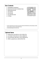
Contents GA-M61PME-S2 motherboard Motherboard driver disk (For Windows Vista) Motherboard driver disk User's Manual One IDE motherboard image is for reference only. Optional Items Floppy disk drive cable (Part No. 12CF1-1FD001-7*R) 2-port USB 2.0 bracket (Part No. 12CR1-1UB030-5*R) 2-port SATA power - Gigabyte GA-M61PME-S2 | Manual - Page 7
GA-M61PME-S2 Motherboard Layout KB_MS ATX_12V Socket AM2 ATX VGA COMA LPT R_USB CPU_FAN USB LAN IT8716 GA-M61PME-S2 CI AUDIO F_AUDIO IDE PCIE_16 DDRII_1 DDRII_2 BIOS PCIE_1 Realtek 8201CL PCI1 CLR_CMOS BATTERY CD_IN PCI2 CODEC SPDIF_IO FDD NVIDIA® GeForce 6100/ nForce 430 - Gigabyte GA-M61PME-S2 | Manual - Page 8
PCIe CLK (100 MHz) AMD Socket AM2 CPU CPU CLK+/-(200 MHz) DDR2 800/667/533 MHz DIMM Dual Channel Memory Hyper Transport Bus PCI Express x16 PCI Express x1 Bus D-Sub x1 PCIe CLK (100 MHz) 1 PCI Express x1 LAN RJ45 Realtek 8201CL NVIDIA® GeForce 6100/ nForce 430 8 USB Ports 2 SATA 3Gb/s ATA - Gigabyte GA-M61PME-S2 | Manual - Page 9
discharge (ESD) wrist strap when handling electronic components such as a motherboard, CPU or memory. If you do not have an ESD wrist strap, power supply cable from the motherboard, make sure the power supply has been turned off. • Before turning on the power, make sure the power supply - Gigabyte GA-M61PME-S2 | Manual - Page 10
2 x SATA 3Gb/s connectors 1 x CPU fan header 1 x system fan header 1 x front panel header 1 x front panel audio header 1 x CD In connector 1 x S/PDIF Out header 2 x USB 2.0/1.1 headers 1 x chassis intrusion header 1 x power LED header GA-M61PME-S2 Motherboard - 10 - - Gigabyte GA-M61PME-S2 | Manual - Page 11
BIOS 2.4, ACPI 1.0b Support for @BIOS Support for Download Center Support for Q-Flash Support for EasyTune (Note 3) Support for Xpress Install Support for Xpress Recovery2 Support for Virtual Dual BIOS Norton Internet Security (OEM version) Support for Microsoft® Windows® Vista/XP - Gigabyte GA-M61PME-S2 | Manual - Page 12
card, memory, hard drive, etc. 1-3-1 Installing the CPU A. Locate the pin one (denoted by a small triangle) of the CPU socket and the CPU. A Small Triangle Mark Denotes Pin One of the Socket AM2 CPU Socket A Small Triangle Marking Denotes CPU Pin One AM2 CPU GA-M61PME-S2 Motherboard - 12 - - Gigabyte GA-M61PME-S2 | Manual - Page 13
to correctly install the CPU into the motherboard CPU socket. Before installing the CPU, make sure to turn off the computer and unplug the power cord from the power outlet to prevent damage to the CPU. CPU Socket Locking Lever Step 1: Completely lift up the CPU socket locking lever. Step 2: Align - Gigabyte GA-M61PME-S2 | Manual - Page 14
attach the power connector of the CPU cooler to the CPU fan header (CPU_FAN) on the motherboard. Use extreme care when removing the CPU cooler because the thermal grease/tape between the CPU cooler and CPU may adhere to the CPU. Inadequately removing the CPU cooler may damage the CPU. GA-M61PME-S2 - Gigabyte GA-M61PME-S2 | Manual - Page 15
Make sure that the motherboard supports the memory. It is recommended that memory of the same capacity, brand, speed, and chips be used. (Go to GIGABYTE's website for the latest memory support list.) • Always turn off the computer and unplug the power cord from the power outlet before installing the - Gigabyte GA-M61PME-S2 | Manual - Page 16
on the left, place your fingers on the top edge of the memory, push down on the memory and insert it vertically into the memory socket. Step 2: The clips at both ends of the socket will snap into place when the memory module is securely inserted. GA-M61PME-S2 Motherboard - 16 - - Gigabyte GA-M61PME-S2 | Manual - Page 17
motherboard supports the expansion card. Carefully read the manual that came with your expansion card. • Always turn off the computer and unplug the power cord from the power , go to BIOS Setup to make any required BIOS changes for your expansion card(s). 7. Install the driver provided with the - Gigabyte GA-M61PME-S2 | Manual - Page 18
. Connect a monitor that supports D-Sub connection to this port. USB Port The USB port supports the USB 2.0/1.1 specification. Use this port for USB devices such as an USB keyboard/mouse, USB printer, USB flash drive and etc. RJ-45 LAN Port The Fast Ethernet LAN port provides Internet connection - Gigabyte GA-M61PME-S2 | Manual - Page 19
speakers in a 4/5.1-channel audio configuration. Mic In Jack (Pink) The default Mic in jack. Microphones must be connected to this jack. Refer to the instructions on setting up a 2/4/5.1-channel audio configuration in Chapter 5, "Configuring 2/4/5.1-Channel Audio." - 19 - Hardware Installation - Gigabyte GA-M61PME-S2 | Manual - Page 20
the devices and your computer. Unplug the power cord from the power outlet to prevent damage to the devices. • After installing the device and before turning on the computer, make sure the device cable has been securely attached to the connector on the motherboard. GA-M61PME-S2 Motherboard - 20 - - Gigabyte GA-M61PME-S2 | Manual - Page 21
an unstable or unbootable system. • The main power connector is compatible with power supplies with 2x10 power connectors. When using a 2x12 power supply, remove the protective cover from the main power connector on the motherboard. Do not insert the power supply cable into pins under the protective - Gigabyte GA-M61PME-S2 | Manual - Page 22
drives supported are: 360 KB, 720 KB, 1.2 MB, 1.44 MB, and 2.88 MB. Before connecting a floppy disk drive, be sure to locate pin 1 of the connector and the floppy disk drive cable. The pin 1 of the cable is typically designated by a stripe of different color. 33 1 34 2 GA-M61PME-S2 Motherboard - Gigabyte GA-M61PME-S2 | Manual - Page 23
a single SATA device. The NVIDIA® GeForce 6100/ nForce 430 chipset controller supports RAID 0 and RAID 1. Refer to Chapter 5, "Configuring SATA Hard Drive(s)," for instructions on configuring a RAID array. SATAII0 7 1 1 7 SATAII1 Pin No. 1 2 3 4 5 6 7 Definition GND TXP TXN GND RXN RXP - Gigabyte GA-M61PME-S2 | Manual - Page 24
LED S0 On S1 Blinking S3/S4/S5 Off 9) BATTERY The battery provides power to keep the values (such as BIOS configurations, date, and time information) in the CMOS when the computer is turned must be handled in accordance with local environmental regulations. GA-M61PME-S2 Motherboard - 24 - - Gigabyte GA-M61PME-S2 | Manual - Page 25
beep code. One single short beep will be heard if no problem is detected at system startup. If a problem is detected, the BIOS may issue beeps in different patterns to indicate the problem. Refer to Chapter 5, "Troubleshooting," for information about beep of power switch, reset switch, power LED, - Gigabyte GA-M61PME-S2 | Manual - Page 26
front panel audio module that has different wire assignments, please contact the chassis manufacturer. 12) CD_IN (CD In Connector) You may connect the audio cable that came with your optical drive to the header. Pin No. Definition 1 CD-L 2 GND 1 3 GND 4 CD-R GA-M61PME-S2 Motherboard - 26 - Gigabyte GA-M61PME-S2 | Manual - Page 27
PDIF out. Via an optional S/PDIF out cable, this header can connect to an audio device that supports digital audio in. For purchasing the optional S/PDIF out cable, please contact the local dealer. Pin No. Definition 1 Power 1 2 SPDIFO 3 GND Pin 1 (the red wire) of the S/PDIF out cable must - Gigabyte GA-M61PME-S2 | Manual - Page 28
BIOS configurations) and reset power cord from the power motherboard. • After system restart, go to BIOS Setup to load factory defaults (select Load Optimized Defaults) or manually configure the BIOS settings (refer to Chapter 2, "BIOS Setup," for BIOS configurations). GA-M61PME-S2 Motherboard - Gigabyte GA-M61PME-S2 | Manual - Page 29
the GIGABYTE Q-Flash or @BIOS utility. • Q-Flash allows the user to quickly and easily upgrade or back up BIOS without entering the operating system. • @BIOS is a Windows-based utility that searches and downloads the latest version of BIOS from the Internet and updates the BIOS. For instructions on - Gigabyte GA-M61PME-S2 | Manual - Page 30
, the device boot order will still be based on BIOS Setup settings. You can access Boot Menu again to change the first boot device setting as needed. : Q-Flash Press the key to access the Q-Flash utility directly without having to enter BIOS Setup first. GA-M61PME-S2 Motherboard - 30 - - Gigabyte GA-M61PME-S2 | Manual - Page 31
Version: D1a) CMOS Setup Utility-Copyright (C) 1984-2007 Award Software Standard CMOS Features Advanced BIOS Features Integrated Peripherals Power Management Setup PnP/PCI Configurations PC Health Status Load Fail-Safe Defaults Load Optimized Defaults Set Supervisor Password Set User - Gigabyte GA-M61PME-S2 | Manual - Page 32
BIOS Features Use this menu to configure the device boot order, advanced features available on the CPU, and the primary display adapter. Integrated Peripherals Use this menu to configure all peripheral devices, such as IDE, SATA, USB, integrated audio, and integrated LAN, etc. Power Management - Gigabyte GA-M61PME-S2 | Manual - Page 33
Features Fri, Dec 28 2007 11:52:24 Item Help Menu Level IDE Drive A Floppy 3 Mode Support [1.44M, 3.5"] [Disabled] • Auto Lets BIOS automatically detect IDE/ Manual skip the detection of the device during the POST for faster system startup. Allows you to manually enter the specifications - Gigabyte GA-M61PME-S2 | Manual - Page 34
specifications. If you wish to enter the parameters manually Floppy 3 Mode Support Allows you to BIOS POST. Base Memory Also called conventional memory. Typically, 640 KB will be reserved for the MS-DOS operating system. Extended Memory The amount of extended memory. GA-M61PME-S2 Motherboard - Gigabyte GA-M61PME-S2 | Manual - Page 35
can function as multiple virtual systems. (Default: Disabled) AMD K8 Cool&Quiet control Auto Lets the AMD Cool'n'Quiet driver dynamically adjust the CPU clock and VIA to Disabled reduce heat output from your computer and its power consumption. (Default) Disable this function. Hard Disk Boot - Gigabyte GA-M61PME-S2 | Manual - Page 36
Enables or disables Away Mode in Windows XP Media Center operating system. Away Mode allows the system to silently perform unattended tasks while in a low-power mode that appears off (Default: to set up a dual view configuration, set this item to Always Enable. GA-M61PME-S2 Motherboard - 36 - - Gigabyte GA-M61PME-S2 | Manual - Page 37
Onboard Audio Function On-Chip MAC Lan Onboard LAN Boot ROM Onboard Serial Port 1 Onboard Parallel Port Parallel Port Mode x ECP Mode Use DMA On-Chip USB USB Keyboard Support USB Mouse Support Legacy USB storage -Safe Defaults ESC: Exit F1: General Help F7: Optimized Defaults - 37 - BIOS Setup - Gigabyte GA-M61PME-S2 | Manual - Page 38
. V1.1+V2.0 Enables the integrated USB 1.1 and USB 2.0 controllers. (Default) V1.1 Disabled Enables only the integrated USB 1.1 controller. Disables the integrated USB 1.1 and USB 2.0 controllers. Disabled will turn off all of the USB functionalities below. GA-M61PME-S2 Motherboard - 38 - - Gigabyte GA-M61PME-S2 | Manual - Page 39
to be used in MS-DOS. (Default: Disabled) USB Mouse Support Allows USB mouse to be used in MS-DOS. (Default: Disabled) Legacy USB storage detect Determines whether to detect USB storage devices, including USB flash drives and USB hard drives during the POST. (Default: Enabled) - 39 - BIOS Setup - Gigabyte GA-M61PME-S2 | Manual - Page 40
PCI or PCIe device. Note: To use this function, you need an ATX power supply providing at least 1A on the 5VSB lead. (Default: Enabled) Modem Ring modem that supports wake-up function. (Default: Enabled) (Note) Supported on Windows® Vista® operating system only. GA-M61PME-S2 Motherboard - 40 - - Gigabyte GA-M61PME-S2 | Manual - Page 41
: you need an ATX power supply providing at least 1A on power from an AC power loss. Soft-Off The system stays off upon the return of the AC power. (Default) Full-On The system is turned on upon the return of the AC power. (Note) Supported on Windows® Vista® operating system only. - 41 - BIOS - Gigabyte GA-M61PME-S2 | Manual - Page 42
Help F7: Optimized Defaults BIOS auto-assigns IRQ to the first PCI slot. (Default) Assigns IRQ 3,4,5,7,9,10,11,12,14,15 to the first PCI slot. BIOS auto-assigns IRQ to the second PCI slot. (Default) Assigns IRQ 3,4,5,7,9,10,11,12,14,15 to the second PCI slot. GA-M61PME-S2 Motherboard - 42 - - Gigabyte GA-M61PME-S2 | Manual - Page 43
device attached to the motherboard CI header. If the intrusion status record, set Reset Case Open Status to Enabled CPU temperature. When system/CPU temperature exceeds the threshold, BIOS will emit warning sound. Options are: Disabled (default), 60oC/140oF, 70oC/158oF, 80oC/176oF, 90oC/194oF. CPU - Gigabyte GA-M61PME-S2 | Manual - Page 44
configurable only if CPU Smart FAN Control is set to Enabled. Auto Lets BIOS autodetect the type of CPU fan installed and sets the optimal CPU fan control mode. (Default) Voltage Sets Voltage mode for a 3-pin CPU fan. PWM Sets PWM mode for a 4-pin CPU fan. GA-M61PME-S2 Motherboard - 44 - - Gigabyte GA-M61PME-S2 | Manual - Page 45
, which are the safest and most stable BIOS settings for the motherboard. 2-10 Load Optimized Defaults CMOS Setup Utility-Copyright (C) 1984-2007 Award Software Standard CMOS Features Advanced BIOS Features Integrated Peripherals Power Management Setup PnP/PCI Configurations PC Health - Gigabyte GA-M61PME-S2 | Manual - Page 46
you to view the BIOS settings but not to make changes. To clear the password, press on the password item and when requested for the password, press again. The message "PASSWORD DISABLED" will appear, indicating the password has been cancelled. GA-M61PME-S2 Motherboard - 46 - - Gigabyte GA-M61PME-S2 | Manual - Page 47
Menu. 2-13 Exit Without Saving CMOS Setup Utility-Copyright (C) 1984-2007 Award Software Standard CMOS Features Advanced BIOS Features Integrated Peripherals Power Management Setup PnP/PCI Configurations PC Health Status Esc: Quit F8: Q-Flash Load Fail-Safe Defaults Load Optimized - Gigabyte GA-M61PME-S2 | Manual - Page 48
GA-M61PME-S2 Motherboard - 48 - - Gigabyte GA-M61PME-S2 | Manual - Page 49
Installing Chipset Drivers After inserting the driver disk, "Xpress Install" will automatically scan the system and then list all the drivers that are in the motherboard driver disk. • For USB 2.0 driver support under the Windows XP operating system, please install the Windows XP Service Pack 1 - Gigabyte GA-M61PME-S2 | Manual - Page 50
all the tools and applications that GIGABYTE develops and some free software. You may press the Install button following an item to install it. 3-3 Driver CD Information This page provides information about the drivers, applications and tools in this driver disk. GA-M61PME-S2 Motherboard - 50 - - Gigabyte GA-M61PME-S2 | Manual - Page 51
3-4 Hardware Information This page provides information about the hardware devices on this motherboard. 3-5 Contact Us Check the contacts information of the GIGABYTE headquarter in Taiwan and the overseas branch offices on the last page of this manual. - 51 - Drivers Installation - Gigabyte GA-M61PME-S2 | Manual - Page 52
GA-M61PME-S2 Motherboard - 52 - - Gigabyte GA-M61PME-S2 | Manual - Page 53
after the operating system and drivers are installed. • The amount of Windows® XP with SP1 or later • Xpress Recovery and Xpress Recovery2 are different utilities. For example, a backup file created with Xpress Recovery cannot be restored using Xpress Recovery2. • USB hard drives are not supported - Gigabyte GA-M61PME-S2 | Manual - Page 54
Windows XP as the example operating system.) A. Installing Windows XP and Partitioning the Hard Drive 1. Set CD-ROM drive as the first boot device under "Advanced BIOS Features" in the BIOS ) and begin the installation of the operating system (Figure 3). Figure 3 GA-M61PME-S2 Motherboard - 54 - - Gigabyte GA-M61PME-S2 | Manual - Page 55
4. After the operating system is installed, right-click the My Computer icon on your desktop and select Manage (Figure 4). Go to Computer Management to check disk allocation. Xpress Recovery2 will save the backup file to the unallocated space (black stripe along the top)(Figure 5). Please note that - Gigabyte GA-M61PME-S2 | Manual - Page 56
drive contains the Windows operating system. When the Windows operating system is detected, Xpress Recovery2 will begin the backup process (Figure 11). Figure 10 Figure 11 3. When finished, go to Disk Management to check disk allocation. Figure 12 GA-M61PME-S2 Motherboard Xpress Recovery2 will - Gigabyte GA-M61PME-S2 | Manual - Page 57
D. Using the Restore Function in Xpress Recovery2 Select RESTORE to restore the backup to your hard drive in case the system breaks down. The RESTORE option will not be present if no backup is created before (Figure 13, 14). Figure 13 Figure 14 E. Removing the Backup 1. If you wish to remove the - Gigabyte GA-M61PME-S2 | Manual - Page 58
. M61PME-S2 D1a . . . . : BIOS Setup/Q-Flash : XpressRecovery2 : Boot Menu : Qflash 12/17/2007-NV-MCP61-6A61KG09C-00 Because BIOS flashing is potentially risky, please do it with caution. Inadequate BIOS flashing may result in system malfunction. GA-M61PME-S2 Motherboard - 58 - Gigabyte GA-M61PME-S2 | Manual - Page 59
0-0 Keep DMI Data Enable Update BIOS from Drive Sa0vefilBeI(Os)SfotounDdrive :Move ESC:Reset :Power Off Total size : 0 Free size : 0 3. Select the BIOS update file and press . Make sure the BIOS update file matches your motherboard model. Step 2: The process of - Gigabyte GA-M61PME-S2 | Manual - Page 60
Standard CMOS Features Advanced BIOS Features Integrated Peripherals Power Management Setup PnP/PCI BIOS defaults Step 6: Select Save & Exit Setup and then press to save settings to CMOS and exit BIOS Setup. The procedure is complete after the system restarts. GA-M61PME-S2 Motherboard - Gigabyte GA-M61PME-S2 | Manual - Page 61
and Using @BIOS: Use the motherboard driver disk included with the motherboard to install @BIOS. • Installing the @BIOS utility. • Accessing the @BIOS utility. Click Start>All Programs>GIGABYTE>@BIOS Select @BIOS and click Install. C. Options and Instructions: 1. Save the Current BIOS File In - Gigabyte GA-M61PME-S2 | Manual - Page 62
could result in an unbootable system. • If the BIOS update file for your motherboard is not present on the @BIOS server site, please manually download the BIOS update file from GIGABYTE's website and follow the instructions in "Update the BIOS without Using the Internet Update Function" below. Step - Gigabyte GA-M61PME-S2 | Manual - Page 63
the BIOS Setup program. EasyTune 5 provides the following functions (Note 1): overclocking/overvoltage, C.I.A./ M.I.B. (Note 2), smart fan control, and hardware monitoring and warning. (For instructions on using EasyTune5, read or download the information on/from the Support\Motherboard\Utility - Gigabyte GA-M61PME-S2 | Manual - Page 64
the slider or spin box. Click Apply and then OK to turn on ReadyBoost. • The USB flash drive must have at least 256 MB of space. • The recommended amount of memory to use for ReadyBoost acceleration is one to three times the amount of RAM installed in your computer. GA-M61PME-S2 Motherboard - 64 - - Gigabyte GA-M61PME-S2 | Manual - Page 65
BIOS Setup. C . Configure a RAID array in RAID BIOS. (Note) D. Make a floppy disk containing the SATA RAID driver. (Note) E. Install the SATA RAID driver . • Windows Vista/XP/2000 setup disk. • Motherboard driver disk. on the motherboard. Then connect the power connector from your power supply to the - Gigabyte GA-M61PME-S2 | Manual - Page 66
Step 2: Save changes and exit BIOS Setup. The BIOS Setup menus described in this section may differ from the exact settings for your motherboard. The actual BIOS Setup menu options you will see shall depend on the motherboard you have and the BIOS version. GA-M61PME-S2 Motherboard - 66 - - Gigabyte GA-M61PME-S2 | Manual - Page 67
BIOS Enter the RAID BIOS setup utility to configure a RAID array. For a non-RAID configuration, please skip this step and proceed to the installation of Windows select a RAID mode. The supported RAID modes include Mirroring, Striping, Striping) is selected, you can manually set the stripe block size. - Gigabyte GA-M61PME-S2 | Manual - Page 68
d[iNsk] NdaO1ta.0?.M ST3120026AS [] Add 1.1.M ST3120026AS [Y] YES [N] NO [] Del Capacity 111.79GB 111.79GB [ESC] Quit [F6] Back [F7] Finish [TAB] Navigate [] Select [ENTER] Popup Figure 6 GA-M61PME-S2 Motherboard - 68 - - Gigabyte GA-M61PME-S2 | Manual - Page 69
have created (Figure 7). Boot No MediaShield Utility Nov 20 2006 - Array List - Status Vendor Array Model Name Healthy NVIDIA STRIPE 223.57G [Ctrl-X] to cancel. Press to return to the Array List screen. To exit the NVIDIA RAID setup utility, press in the main menu or - Gigabyte GA-M61PME-S2 | Manual - Page 70
users without a startup disk: Use an alternative system and insert the motherboard driver disk. From your optical drive folder, double click the MENU.exe file in the BootDrv folder (Figure 3). A command prompt window will open similar to that in Figure 2. GA-M61PME-S2 Motherboard Figure 3 - 70 - - Gigabyte GA-M61PME-S2 | Manual - Page 71
and Operating System Now that you have prepared the SATA RAID driver diskette for Windows XP/2000 and configured the required BIOS settings, you are ready to install the operating system onto your hard drive(s). Please note that installation of Windows Vista does not require you to install the RAID - Gigabyte GA-M61PME-S2 | Manual - Page 72
for use with Windows, press ENTER. S=Specify Additional Device Enter=Continue F3=Exit Figure 4 If a message appears saying one or some file(s) cannot be found, please check the floppy disk or copy the correct SATA RAID driver again from the motherboard driver disk. GA-M61PME-S2 Motherboard - 72 - - Gigabyte GA-M61PME-S2 | Manual - Page 73
Step 4: After the SATA controller driver installation is completed, you can proceed with the Windows XP installation. WindowsXP Professional Setup Welcome to Setup. This port of the Setup program prepares Microsoft(R) Windows (R) XP to run on your computer. To set up Windows XP now, press ENTER. To - Gigabyte GA-M61PME-S2 | Manual - Page 74
: Refer to the following for multi-channel speaker configurations. • 2-channel audio: Headphone or Line out. • 4-channel audio: Front speaker out and Rear speaker out. • 5.1-channel audio: Front speaker out, Rear speaker out, and Center/Subwoofer speaker out. GA-M61PME-S2 Motherboard - 74 - - Gigabyte GA-M61PME-S2 | Manual - Page 75
Step 2: Click the Audio I/O tab. In the speaker list on the left, select 2CH Speaker, 4CH Speaker, or 6CH Speaker Out Rear Speaker Out 5.1-Channel Speakers: Step 4: Everytime you connect an audio device to an audio jack, the Connected device box appears. Select the device according to the type - Gigabyte GA-M61PME-S2 | Manual - Page 76
detection check box. Click OK to complete. D. Muting the Back Panel Audio (For HD Audio Only): Click the tool icon on the Audio I/O tab. On the Connector Settings box, select the Mute rear panel output when front headphone plugged in check box. Click OK to complete. GA-M61PME-S2 Motherboard - 76 - - Gigabyte GA-M61PME-S2 | Manual - Page 77
in and out cable first if you want to output S/PDIF digital audio signals to an external decoder. A. Installing the S/PDIF Out Cable: Step 1: First, attach the connector at the end of the cable to the SPDIF_IO header on your motherboard. Pin 1 (the red wire) of the S/PDIF out cable must align - Gigabyte GA-M61PME-S2 | Manual - Page 78
digital audio signals. S/PDIF Optical Cable B. Configuring S/PDIF out: Click the tool icon in the DIGITAL section. In the S/PDIF Settings dialog box, select an output sampling rate and select (or disable) the output source. Click OK to complete the configuration. GA-M61PME-S2 Motherboard - 78 - Gigabyte GA-M61PME-S2 | Manual - Page 79
5-2-3 Configuring Microphone Recording Step 1: After installing the audio driver, the Audio Manager icon will appear in your system tray. Double-click the icon to access the Audio Control Panel. Step 2: Connect your microphone to the Mic in jack (pink) on the back panel or the Line in jack on the - Gigabyte GA-M61PME-S2 | Manual - Page 80
Mixer device list, select Realtek HD Audio Input. Then set the recording sound level properly. Do NOT mute the recording sound, or you will not hear any sound when playing back the recording you just made. Select Realtek HD Audio Input in the Mixer device list GA-M61PME-S2 Motherboard Recording - Gigabyte GA-M61PME-S2 | Manual - Page 81
to All Programs, point to Accessories, point to Entertainment, and then click Sound Recorder to begin the sound recording. 5-2-4 Using the Sound Recorder Recording the Sound: 1. Make sure you have connected the audio input device (e.g. microphone) to the computer. 2. On the File menu, choose New - Gigabyte GA-M61PME-S2 | Manual - Page 82
setting error 1 long, 1 short: Memory or motherboard error 1 long, 2 short: Monitor or graphics card error 1 long, 3 short: Keyboard error 1 long, 9 short: BIOS ROM error Continuous long beeps: Graphics card not inserted properly Continuous short beeps: Power error GA-M61PME-S2 Motherboard - 82 - - Gigabyte GA-M61PME-S2 | Manual - Page 83
and solved. Secure the CPU No cooler on the CPU. Connect the CPU cooler power cable to the motherboard. The problem is verified and solved. No Correctly insert the memory into the memory socket. The problem is verified and solved. Press to enter BIOS Setup. Select "Load Fail - Gigabyte GA-M61PME-S2 | Manual - Page 84
power supply, CPU or CPU socket might fail. The problem is verified and problem, contact the place of purchase or local dealer for help. Or go to the Support\Technical Service Zone page to submit your question. Our customer service staff will reply you as soon as possible. GA-M61PME-S2 Motherboard - Gigabyte GA-M61PME-S2 | Manual - Page 85
GIGABYTE. Our Commitment to Preserving the Environment In addition to high-efficiency performance, all GIGABYTE motherboards office, your household waste disposal service or where you purchased the Customer Care number listed in your product's user's manual and we will be glad to help you - Gigabyte GA-M61PME-S2 | Manual - Page 86
hazardous substances are not released into the environment and are disposed of properly. China Restriction of Hazardous Substances Table The following table is supplied in compliance with China's Restriction of Hazardous Substances (China RoHS) requirements: GA-M61PME-S2 Motherboard - 86 - - Gigabyte GA-M61PME-S2 | Manual - Page 87
- 87 - Appendix - Gigabyte GA-M61PME-S2 | Manual - Page 88
GA-M61PME-S2 Motherboard - 88 - - Gigabyte GA-M61PME-S2 | Manual - Page 89
- 89 - Appendix - Gigabyte GA-M61PME-S2 | Manual - Page 90
GA-M61PME-S2 Motherboard - 90 - - Gigabyte GA-M61PME-S2 | Manual - Page 91
- 91 - Appendix - Gigabyte GA-M61PME-S2 | Manual - Page 92
GA-M61PME-S2 Motherboard - 92 - - Gigabyte GA-M61PME-S2 | Manual - Page 93
- 93 - Appendix - Gigabyte GA-M61PME-S2 | Manual - Page 94
GA-M61PME-S2 Motherboard - 94 - - Gigabyte GA-M61PME-S2 | Manual - Page 95
231, Taiwan TEL: +886-2-8912-4888 FAX: +886-2-8912-4003 Tech. and Non-Tech. Support (Sales/Marketing) : http://ggts.gigabyte.com.tw WEB address (English): http://www.gigabyte.com.tw WEB address (Chinese): http://www.gigabyte.tw G.B.T. INC. - U.S.A. TEL: +1-626-854-9338 FAX: +1-626-854-9339 Tech - Gigabyte GA-M61PME-S2 | Manual - Page 96
language in the language list on the top right corner of the website. GIGABYTE Global Service System To submit a technical or non-technical (Sales/ Marketing) question, please link to : http://ggts.gigabyte.com.tw Then select your language to enter the system. GA-M61PME-S2 Motherboard - 96 -
-
 1
1 -
 2
2 -
 3
3 -
 4
4 -
 5
5 -
 6
6 -
 7
7 -
8
-
9
-
10
-
11
-
12
-
13
-
14
-
15
-
16
-
17
-
18
-
19
-
20
-
21
-
22
-
23
-
24
-
25
-
26
-
27
-
28
-
29
-
30
-
31
-
32
-
33
-
34
-
35
-
36
-
37
-
38
-
39
-
40
-
41
-
42
-
43
-
44
-
45
-
46
-
47
-
48
-
49
-
50
-
51
-
52
-
53
-
54
-
55
-
56
-
57
-
58
-
59
-
60
-
61
-
62
-
63
-
64
-
65
-
66
-
67
-
68
-
69
-
70
-
71
-
72
-
73
-
74
-
75
-
76
-
77
-
78
-
79
-
80
-
81
-
82
-
83
-
84
-
85
-
86
-
87
-
88
-
89
-
90
-
91
-
92
-
93
-
94
-
95
-
96
 |
 |

GA-M61PME-S2
AM2 socket motherboard for
AMD Athlon
TM
64 FX processor/
AMD Athlon
TM
64 X2 Dual-Core processor/
AMD Athlon
TM
64 processor/AMD Sempron
TM
processor
User's Manual
Rev. 2003
12ME-M61PMES2-2003R