Haier AB072XCEAA Service Manual
Haier AB072XCEAA Manual
 |
View all Haier AB072XCEAA manuals
Add to My Manuals
Save this manual to your list of manuals |
Haier AB072XCEAA manual content summary:
- Haier AB072XCEAA | Service Manual - Page 1
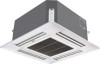
SERVICE MANUAL E-Multi series 4-WAY CASSETTE INDOOR UNIT DUCT INDOOR UNIT CONSOLE INDOOR UNIT WALL MOUNTED INDOOR UNIT OUTDOOR UNIT(28/42000BTU/h) Haier Commercial Air Conditioner Version: 200808 SYJS-018-07REV.1 - Haier AB072XCEAA | Service Manual - Page 2
5.5 Wall mounted type 14 5.6 AU282XHEAA 15 5.7 AU422XIEAA 15 6. Refrigerant diagram 16 6.1 AU282XHEAA 16 6.2 AU422XIEAA 17 7. The unit capacity 68 10. Trouble shooting 76 11. Outdoor performance curves 77 12. indoor air velocity and temperature distribution curves 79 13. Air flow and static - Haier AB072XCEAA | Service Manual - Page 3
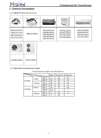
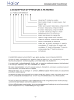
1. General information 1.1 E-Multi (R410a) series line up Chff^j\bZe Abj Chg]blbhg^j AB072XCEAA AB092XCEAA AB122XCEAA AB142XCEAA AB212XCEAA AD072XLEAA AD092XLEAA AD122XLEAA AD142XLEAA AD212XLEAA AF072XCEAA AF092XCEAA AF122XCEAA AF142XCEAA AS072XCEAA AS092XCEAA AS122XCEAA AS142XCEAA AU282XHEAA - Haier AB072XCEAA | Service Manual - Page 4
refrigerant is R22 B stands for heat pump type, refrigerant is R407C E stands for heat pump type, refrigerant is R410A Q stands for cool only type, refrigerant stands for ceiling concealed type, "U" stands for outdoor unit Air Conditioner 2.2 Product character 2.2.1 Phylogeny E-Multi(R410A) series is - Haier AB072XCEAA | Service Manual - Page 5
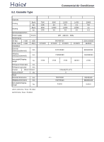
R410a and solve problems. 3. Specification 3.1. Air flow H Noise Level H/M/L Installation External dimensions(WxHxD) Btu/h kw Btu/h kw Ph/V/Hz kw kw m3/h dB(A) mm Shipping dimensions(WxHxD) mm Net weight/Shipping weight kg Compressor type Scroll/Rotary Refrigerant type Refrigerant - Haier AB072XCEAA | Service Manual - Page 6
Model Heating Electrical parameters Power supply Performance Air flow Noise Level Installation H/M/L H/M/L External dimensions kg 17/20 17/20 17/20 19/23.5 27/33 Refrigerant liquid pipe mm Refrigerant gas pipe mm Control Wired /Infrared Static pressure Pa Panel External - Haier AB072XCEAA | Service Manual - Page 7
22000 6.4 Electrical parameters Power supply Ph/V/Hz 1PH 230VAC 50Hz Performance Air flow H/M/L m3/h 560/450/360/300 820/700/600/500 weight kg 18/20 18/20 20/22 20/22 28/32 Refrigerant liquid pipe mm Refrigerant gas pipe mm Control Wired /Infrared Static pressure Pa 6.35 9. - Haier AB072XCEAA | Service Manual - Page 8
kw Btu/h kw Ph/V/Hz AF072XCEAA 7000 2.05 8000 2.35 Air flow H/M/L m3/h 500/400/320 Noise Level H/M/L Installation External dimensions kg 15.5/19 15.5/19 17/20.7 17/20.7 Refrigerant liquid pipe mm 6.35 6.35 6.35 6.35 Refrigerant gas pipe mm 9.52 9.52 9.52 9.52 Control Wired - Haier AB072XCEAA | Service Manual - Page 9
Electrical parameters Power supply Performance Air flow H/M/L Noise Level l H/M/L Installation External dimensions(WxHxD) Shipping dimensions(WxHxD) Btu/h kw Btu/h kw Ph/V/Hz m3/h dB(A) mm mm Net weight/Shipping weight kg Refrigerant liquid pipe mm Refrigerant gas pipe mm Control - Haier AB072XCEAA | Service Manual - Page 10
4.2. Outdoor unit: AU422XIEAA Chff^j\bZe Abj Chg]blbhg^j Terminal block screw hole (M10) z 8 z - Haier AB072XCEAA | Service Manual - Page 11
4.3. Cassette Type AB07-142XCEAA Chff^j\bZe Abj Chg]blbhg^j Distance between suspending bolts 535mm Indoor unit 570mm Ceiling opening 650mm Ornament panel 700mm 4.4. Wall Mounted Type AS07-142XCEAA c model a b c AS072XCEAA AS092XCEAA E 7 9 5 2 6 5 1 8 2 AS122XCEAA AS142XCEAA EEE z 9 z - Haier AB072XCEAA | Service Manual - Page 12
4.5. Model: AB212XCEAA Chff^j\bZe Abj Chg]blbhg^j z 10 z - Haier AB072XCEAA | Service Manual - Page 13
Chff^j\bZe Abj Chg]blbhg^j 4.6. Duct Type AD***XLEAA Figure showing installation dimensions: (unit:mm) Model Series 07-09 abcdef gi 615 648 450 220 80 125 225 100 Series 12-14 770 804 450 220 80 125 225 100 Series 18-21 1060 1120 450 220 80 125 225 100 i 4.7. Console Type AF***XCEAA 720 630 - Haier AB072XCEAA | Service Manual - Page 14
by using the SWING button on the remote controller) Operating Control Panel Air Inlet Grille Air Filter (Inside of the Inlet Grille) Operating Control Panel 1 2 34 in the outlet) Outlet Air filter (located in the suction grill) Suction grill Refrigerant pipe Cable line Earthing line z 12 z - Haier AB072XCEAA | Service Manual - Page 15
(see the following picture) when shipping from the factory and they are of back-side return air type. During the installation, the unit also can be changed to a Downside Return air according to the user's need. Electrical control box 5.4 Console Type AF***XCEAA 1 2 1.OUTLET 3 2.CONTROL PANEL - Haier AB072XCEAA | Service Manual - Page 16
Chff^j\bZe Abj Chg]blbhg^j 5.5 Wall Mounted Type AS***XCEAA INDOOR UNIT FRONT VIEW Singal receiver window Air inlet grille Air outlet grille Louver Air filter (inside) INDOOR UNIT BACK VIEW Mounting plate Heat preservation pipe Connecting pipes Drainage pipes z 14 z - Haier AB072XCEAA | Service Manual - Page 17
5.6. Outdoor Unit AU282XHEAA 3 1 2 5.7. AU422XIEAA 1 4 3 2 Chff^j\bZe Abj Chg]blbhg^j Air inlet Air outlet Air inlet Service panel 1 Air inlet 2 Air outlet 3 Air inlet 4 Service panel 4 z 15 z - Haier AB072XCEAA | Service Manual - Page 18
Chff^j\bZe Abj Chg]blbhg^j 6. Refrigerant Diagram 6.1. Refrigeration diagram for AU282XHEAA z 16 z outdoor unit Compressor A liquid receiver four-way valve Compressor B four-way valve indoor unit heat exchanger solenoid valve capillary solenoid valve - Haier AB072XCEAA | Service Manual - Page 19
Chff^j\bZe Abj Chg]blbhg^j 6.2. Refrigerant diagram for AU422XIEAA z 17 z - Haier AB072XCEAA | Service Manual - Page 20
Chff^j\bZe Abj Chg]blbhg^j 7. The unit capacity and performance mode: 7.1. AU282XHEAA (A stands for A system, B stands for B system). z 18 z COOLING Comb. 1to2 1to3 1to4 Combinations Unit Unit Unit Unit A1 A2 B1 B2 072 - 072 - 092 - 092 - 072 - 092 - 072 072 - - 092 092 - - 072 092 - - 122 - 122 - Haier AB072XCEAA | Service Manual - Page 21
Chff^j\bZe Abj Chg]blbhg^j z 19 z HEATING Combinations Comb. Unit Unit Unit Unit Rated capacity Output/kW total heating (Nom. heating) capacity(KW) Unit Unit Unit Unit min. rated max. A1 A2 B1 B2 A1 A2 B1 B2 data data data 072 - 072 - 3.50 - 3.50 - 3.50 7.00 7.00 092 - 092 - 3.80 - 3.80 - Haier AB072XCEAA | Service Manual - Page 22
Chff^j\bZe Abj Chg]blbhg^j 7.2. The unit capacity and performance mode for AU422XIEAA: z 20 z COOLING Comb. 1to2 1to3 1to4 Combinations Unit Unit Unit Unit A1 A2 B1 B2 122 - 122 - 122 122 - - 122 - 212 - 212 - 212 - 122 122 212 - 122 122 122 - 122 122 122 122 Rated capacity Output/kW (Nom. - Haier AB072XCEAA | Service Manual - Page 23
customers themselves matcTh the communication wire, and the P and Q are nonpolar, the customers must use shielded communication wires. Special Installation Guide to 21000BTU indoor units on Free Multi system Only for outdoor unit AU422XIEAA working with 21000BTU indoor units 1. Special accessory - Haier AB072XCEAA | Service Manual - Page 24
2. Pipe installations: Chff^j\bZe Abj Chg]blbhg^j 21000BTU indoor unit Gas pipe φ12.7 A1 Liquid pipeφ9.52 A2 Gas pipe φ12.7 B1 Liquid pipeφ9.52 B2 21000BTU indoor unit Note: Though AU422XIEAA can match with the R407C free multi indoor unit, we do not recommend so. Because that will not only - Haier AB072XCEAA | Service Manual - Page 25
the drainage pipe can be arranged well. (3) Place where inlet and outlet air of indoor and outdoor unit will not be blocked. (4) Do not expose (thinner and gasoline) concentrates and retains. (6) Place strong enough to support the unit . (7) No expensive articles such as television and piano below - Haier AB072XCEAA | Service Manual - Page 26
Abj Chg]blbhg^j (3) Install a suspending bolt To support the unit weight ,anchor bolt should be used in tilting against the direction of water drainage,problem may occur on floating water leakage.) Nut (Prepare in feild) In the case of existing ceiling Washer (Prepared in feild) (1)Install unit - Haier AB072XCEAA | Service Manual - Page 27
than that of connecting pipe (Pipe of polythene; size: 25mm; O.D.: 32mm ) Drainpipe should be short, with a downward slope at least 1/100 to prevent air bag from forming. If downward slope of drainpipe cannot be made,lifting pipe shall be installed. Keep a distance of 1-1.5m between suspending bolts - Haier AB072XCEAA | Service Manual - Page 28
Chff^j\bZe Abj Chg]blbhg^j 8.1.6. Installation of Ornament Panel Install ornament panel on indoor unit (1) Check whether indoor unit is horizontal with leveler or polythene pipe filled with water , and check that the dimension of the ceiling opening is correct. Take off the lever gauge before - Haier AB072XCEAA | Service Manual - Page 29
be ensured. No block to air flow. Water drainage is smpoth. Place strong enough to support unit weight. Place where inclination is not evident on ceiling. Enough space for mainenance. Indoor and outdoor unit piping length is within limit. (Refer to Installation Manual for outdoor unit.) Indoor and - Haier AB072XCEAA | Service Manual - Page 30
horizontal compartor or PVC tube with water. (If unit is tilting against the direction of water drainage, problem may occur on floating switch, causing water leakage.) (5) Remove the washer mounlting 2 , and tighten the nut above. (6) Remove the paper pattern. Nut (Prepare in feild) In the case - Haier AB072XCEAA | Service Manual - Page 31
Manual of outdoor unit. Outdoor is precharged with refrigerant. Be sure to see the Fig.1, when connecting and removing piping from unit. For the size of the flare nut, please refer to Table 1. Apply refrigerant downward slope at least 1/100 to prevent air bag from happening. If downward slope can - Haier AB072XCEAA | Service Manual - Page 32
(2) Check if water drainage is smooth after installation. Chff^j\bZe Abj Chg]blbhg^j Charge, through air outlet or inspecting hole, 1200ccd water to see water drainage. After wiring Check water drainage in cooling operation. When wiring is not complete Remove cover - Haier AB072XCEAA | Service Manual - Page 33
must in appliance with local Manual and guide them how to operate unit correctly. Before installation. read also the Installation Manual of indoor unit. With this ornament , 2 or 3 air t bend carelessly the swing flap, or, problem may occur. (1) Remove air inlet grill from ornament panel * 1 Push - Haier AB072XCEAA | Service Manual - Page 34
panel on indoor unit. For indoor unit installation, please refer to Installation Manual. (1) As shown in Fig . 7, match the position of swing Holding Seal 5 _ 8mm Caution Ornament panel If screws are not tighten tight, problems in Fig, 8 might occur. Tighten screws properly. Gas leakage. Gas - Haier AB072XCEAA | Service Manual - Page 35
correctly arranged? Is unit safely grounded? Is wire size correct? Are there any obstacles on air inlet and outlet grill of indoor and outdoor unit? Is record made for piping length and refrigerant charging amount? Unproper installation may cause Unit might fall down, make vibration or noise. This - Haier AB072XCEAA | Service Manual - Page 36
service center or similar personnel to avoid risks. The power supply to the indoor unit shall be laid in complying with the operational instruction manual control wiring and refrigerant piping may be laid and fastened together. Before completion of vacuum pumping of the refrigerant pipe system, do - Haier AB072XCEAA | Service Manual - Page 37
Signal cable H05RN-F 3G (1.0~1.5)mm2 H05RN-F 2X(0.75~1.5)mm2 All the cables shall have got the European authentication certificate. The breaker of the air conditioner should be all-pole switch; and the distance between its two contacts should be no less 3mm. Such means for disconnection must be - Haier AB072XCEAA | Service Manual - Page 38
unit 1. Select suitable places the outlet air can be sent to the entire room the filling amount of the refrigerant, please refer to the installation manual attached with the outdoor noise, vibration or pipe broken and refrigerant leakage (see Figure 6). 4. Support the unit firmly. 5. Change the - Haier AB072XCEAA | Service Manual - Page 39
the wall is more than 150mm. The distance between air duct outlet and air conditioner outlet is according to the length of actually installed air duct and in service behavior of the static pressure terminal: Installation sketch map for long and short air duct is showed below, when connect to short - Haier AB072XCEAA | Service Manual - Page 40
a demand of the air conditioner in the room. flexible joint transitive air duct Indoor unit or static pressure box circular air duct joint of air diffuser air diffuser Fig1: Duct connected 2. Installation of air return duct Use rivets to connect the air return duct to the air return inlet of - Haier AB072XCEAA | Service Manual - Page 41
the only choice). These screws shall be installed as follows with space adapting to air conditioner overall dimensions according to the original building structures. Wooden structure A square wood shall be supported by the beams and then set the suspension screws. Square wood Suspension screw New - Haier AB072XCEAA | Service Manual - Page 42
, the drain pipe shall be processed as specified in the installation manual and shall be thermal insulated to avoid dew generation. Improper hose the drain pipe shall be less than 20 m. In case of long pipe, supports shall be provided every 1.5 2m to prevent wavy form. Central piping shall be laid - Haier AB072XCEAA | Service Manual - Page 43
to the outdoor unit. See the instruction manual attached with the outdoor unit for details. Supplementary refrigerant The refrigerant supplementation shall be as specified in the installation instructions attached with the outdoor unit. The added refrigerant shall be R22. The adding procedure - Haier AB072XCEAA | Service Manual - Page 44
Chff^j\bZe Abj Chg]blbhg^j Vacuum pumping With a vacuum pump, create vacuum from the stop valve of the outdoor unit. Emptying with refrigerant sealed in the outdoor unit is absolutely forbidden. Open all valves Open all the valves on the outdoor unit. Gas leakage detection Check with a leakage - Haier AB072XCEAA | Service Manual - Page 45
less direct sunlight. Place where cool and warm air could be delivered evently to every corner of causing vibration,where the body can be supported sufficiently. To prevent interference, place it at on the floor.As figure 3 shown. Once refrigerant piping and drain piping connections are complete,fill - Haier AB072XCEAA | Service Manual - Page 46
cracks Spanner Spanner Joint Nut Threads on the pipes may be damaged when tightening if the pipes are not well aligned. (4) Pipe connection process Apply refrigeration oil on the end of the pipe to be connected and on the flared section. Align the pipes to be connected and tighten the nut - Haier AB072XCEAA | Service Manual - Page 47
external sleeve of the wires. 1(L) Wiring of indoor unit Wiring diagram of loop terminals Remove air intake screen and take out the front wires. Connect the wires as specified in the above by the same wire. Incorrect wiring may damage air conditioner's control or cause operation failure. z 45 z - Haier AB072XCEAA | Service Manual - Page 48
(1/2") 1.2 ~2.0 Correct Incorrect Lean Damage of flare Crack Partial Too outside Installation inspection and test run: Please operate unit according to this Manual. Items to be checked during test run. Please made a '' '' in '' '' Are there any gas leakage? How is insulation at piping connection - Haier AB072XCEAA | Service Manual - Page 49
to the outdoor unit. See the instruction manual attached with the outdoor unit for details. Supplementary refrigerant The refrigerant supplementation shall be as specified in the installation instructions attached with the outdoor unit. The added refrigerant shall be R22. The adding procedure - Haier AB072XCEAA | Service Manual - Page 50
Chff^j\bZe Abj Chg]blbhg^j Vacuum pumping With a vacuum pump, create vacuum from the stop valve of the outdoor unit. Emptying with refrigerant sealed in the outdoor unit is absolutely forbidden. Open all valves Open all the valves on the outdoor unit. Gas leakage detection Check with a leakage - Haier AB072XCEAA | Service Manual - Page 51
AS***XCEAA) Instructions to installation PRECAUTION installation, the air conditioner shall be electrified Scraper or File 7 Pipe Cutter 14 Refrigeration Oil 8.5.2. Wiring connection 1(N) 2(L) 3 must be replaced by the manufacturer or its service center or professional person (the power supply - Haier AB072XCEAA | Service Manual - Page 52
place Install the indoor unit where the weight of the unit can be supported. Install the indoor unit where the heat source and steam source are outdoor unit can be easily connected. Install the indoor unit where its cold air and hot air can be easily sent to all the comers of the room. Install the - Haier AB072XCEAA | Service Manual - Page 53
left piping Heat insulation material signal wire Piping Drain hose Indoor/outdoor electric cable Change-f or-fresh-air tube Indoor/outdoor electric cord and drain hose must be bound with refrigerant piping by protecting tape Cut away, with a nipper, the lid for piping according to the piping - Haier AB072XCEAA | Service Manual - Page 54
in Fig.18 Fig.2 Insulation tube Wire Cord clamp Screw with special washer Round terminal Terminal board Wire Screw with special washer Round terminal Use VW-1,0.5 to 1.0mm thick, PVC tube as the material to preserve the temperature. The airing direction shall be from bottom to top. z 52 z - Haier AB072XCEAA | Service Manual - Page 55
FAN M MOTOR Y/G MOTOR CAPACITOR RECEIVE FLOAT BOARD SWITCH REMOTE CENTRALIZED CONTROLLER NOTE: 1.THE PARTS IN DASHED FRAME ARE OPTIONAL 2.REFER TO OPERATION MANUAL TO SET BM3 AND BM4 3.USER SHOULD NOT TO SET BM1 AND BM2 W:WHITE B:BLACK BL:BLUE R:RED Y:YELLOW Y/G:YELLOW/GREED TEMP.:TEMPERATURE - Haier AB072XCEAA | Service Manual - Page 56
9.1.2. 0010451869 PCB Photo CN26 CN24 CN8 CN18 CN18 CN15 CN23 CN13 CN5 CN1 CN2 CN3 CN4 CN22 Chff^j\bZe Abj Chg]blbhg^j CN27 CN17 CN16 CN21 CN11 CN14 CN12 CN10 BM4 BM3 BM1 CN7 BM2 CN6 CN20 CN25 CN9 z 54 z - Haier AB072XCEAA | Service Manual - Page 57
Chff^j\bZe Abj Chg]blbhg^j 9.1.3. Dip Switch Functions (For AB072-142XCEAA) Functions of dip switch 1 (BM1) ON : ON , OFF : OFF Description Outdoor unit hasn't PC Outdoor unit is fixed frequency single split unit Outdoor unit is fixed frequency Multi split unit Outdoor unit is inverter type - Haier AB072XCEAA | Service Manual - Page 58
9.1.4.Diagnostic code Diagnostic code for AB072-142XCEAA Chff^j\bZe Abj Chg]blbhg^j z 56 z - Haier AB072XCEAA | Service Manual - Page 59
R:RED Y:YELLOW OR:ORANGE BL:BLUE BR:BROWN Y/G:YELLOW/GREEN NOTE: 1. Parts 1 2 in dashed frame are factory optional . 2. Central controller 3 and fresh air 4 are optional. 3. P16 and P17 are used for room card function ROOM TEMP. SENSOR PIPING TEMP. SENSOR B W Y/G 12 12 3 PQ LN TO POWER - Haier AB072XCEAA | Service Manual - Page 60
Chff^j\bZe Abj Chg]blbhg^j 9.2.2.PCB 0010451847 CN1 CN4 CN5 CN7 LED 4,LED5 CN19 CN20 CN17 CN14 LED1 CN13 CN16 P4 P3 P16, P17 CN10 LED2 CN6 CN8 P2 P1 P7 P5 P8 P9 P6 P10 P11 P12 P13 P14 CN12 CN11 CN15 SW5 SW4 CN21 SW3 SW2 SW1 z 58 z - Haier AB072XCEAA | Service Manual - Page 61
Chff^j\bZe Abj Chg]blbhg^j 9.2.3. 0010451847 PCB Dip Switch Functions Caution: ON is 1, OFF is 0 SW1-SW2: used for indoor unit to set unit address from 1 to 16 SW3-SW5: used for indoor unit to select different functions.(every dip switches are corresponding to J1-J10. SW2-4 logistic relationship - Haier AB072XCEAA | Service Manual - Page 62
Chff^j\bZe Abj Chg]blbhg^j 9.2.4. Diagnostic code Display 1 Display 2 Display 3 1 01 01 2 02 02 Diagnostic description Indoor ambient temp. sensor failure Indoor coil temp. sensor failure 3 4A 11 4 49 12 5 48 10 6 53 14 7 47 22 8 07 06 9 06 05 10 08 21 Outdoor - Haier AB072XCEAA | Service Manual - Page 63
Chff^j\bZe Abj Chg]blbhg^j 9.3.1. Wiring Diagram For AF07-142XCEAA z 61 z - Haier AB072XCEAA | Service Manual - Page 64
9.3.2. PCB Photo PCB 0010451212-Part 1: Chff^j\bZe Abj Chg]blbhg^j Run Time Power CN1 SW1 PCB 0010451212-Part 2: LED1 CN103 CN101 z 62 z - Haier AB072XCEAA | Service Manual - Page 65
Chff^j\bZe Abj Chg]blbhg^j 9.3.3. PCB 0010451212-Part 3: CN8 Led4 CN28 CN7 CN13 CN10 CN27 CN22 CN5 CN6 CN1 CN4 CN2 CN3 CN26 CN21 CN20 CN15 3 z 63 z - Haier AB072XCEAA | Service Manual - Page 66
off, the failure code will disappear. Failure description Room temp. sensor abnormal Indoor coil temp. sensor abnormal (liquid pipe) Refrigerant system abnormal High pressure abnormal (outdoor) Drainage abnormal Communication between indoor and wired controller Indoor fan motor abnormalup Indoor - Haier AB072XCEAA | Service Manual - Page 67
34 R BR GND TERMINAL BLOCK RECEIVER DISPLAY EMERGENCY SWITCH M UP SWING MOTOR M DOWN SWING Detector MOTOR ROOM TEMP. SENSOR PIPING TEMP. SENSOR M Fresh Air Motor Power Supply Connect To Outdoor Unit SW1 and SW3 are used to choose the working state of the wire controller. The detailed - Haier AB072XCEAA | Service Manual - Page 68
9.4.2. 0010451213 PCB Photo CN20 SW1 Chff^j\bZe Abj Chg]blbhg^j CN2 CN10 CN11 CN18 CN13 LED1 CN15(N) CN16(L) CN11 CN1 CN4 CN9 SW2 CN3 CN6 CN5 Notice: Wall mounted AS type diagnostic code is same with console type AF. z 66 z - Haier AB072XCEAA | Service Manual - Page 69
Chff^j\bZe Abj Chg]blbhg^j 9.5.1. Wiring Diagram Outdoor unit: AU282XHEAA, AU422XIEAA Outdoor wiring diagram Capacitor 0010573511 Gas Piping Sensor A Gas Piping Sensor B Piping Sensor A Piping Sensor B Temp. Sensor To Indoor Unit To Power Supply Capacitor H CN5 CN4 CN3 CN2 M CN9 L Fan Motor - Haier AB072XCEAA | Service Manual - Page 70
Chff^j\bZe Abj Chg]blbhg^j 9.5.2. AU282XHEAA and AU422XIEAA PCB Photo 0010451214E LED3 CN CN CN CN CN9 CN25 CN26 CN27 CN28 CN29 CN11 CN23 CN12 CN19 CN1 CN6 LED6 CN24 CN31 heater A heater B CN8 z 68 z - Haier AB072XCEAA | Service Manual - Page 71
:±1℃ *Control characteristic: When Tr≤Ts for the first time, the compressor, 4-way valve and outdoor motor will run; indoor motor will run at anti-cold air mode, after the compressor starts up, the z 69 z - Haier AB072XCEAA | Service Manual - Page 72
mode. When Tr - Haier AB072XCEAA | Service Manual - Page 73
Chff^j\bZe Abj Chg]blbhg^j 9.5.4. Electric funtions of outdoor A.1 Control of the compressor, outdoor motor and 4-way valve A.1.1 Outdoor fan motor control A. When system do not have overheating or over current protection, outdoor fan speed will vary with outdoor ambient temperature, as follows: a. - Haier AB072XCEAA | Service Manual - Page 74
Chff^j\bZe Abj Chg]blbhg^j Changing from heating mode to cooling mode , 3 minutes later, it is shut off. E. In heating mode, when indoor temperature has arrived the set one (sensor is OFF), 4-way valve will be shut off 3 minutes later. A.1.4 Solenoid valve control Cooling mode: After the outdoor - Haier AB072XCEAA | Service Manual - Page 75
Chff^j\bZe Abj Chg]blbhg^j contineously, then the outdoor stops running, and shows failure code. After the communication resumes normal operation and cancel the failure When all indoor units can not communicate normally, it shows communciation malfunction. A.2.4 Solenoid valve control with single - Haier AB072XCEAA | Service Manual - Page 76
Chff^j\bZe Abj Chg]blbhg^j Diagnostic code for outdoor unit (1) The PCB 0010451214 and 0010451848 for FREE-MULTI outdoor unit run the same procedure. Outdoor lamp flash times 1 2 3 4 5 6 7 9 10 11 13 15 Failure description Discharge pipe A overheat Outdoor coil temp. sensor A failure Outdoor - Haier AB072XCEAA | Service Manual - Page 77
10.Trouble shooting: 1 communication error Check the outdoor communication lamps are flashing or not No Chff^j\bZe Abj Chg]blbhg^j Change indoor PCB Yes Check the turn - Haier AB072XCEAA | Service Manual - Page 78
. is over high if the temp. is not very high Change sensor Test the true temp. . if the temp. is really very high Check the refrigeration charging, pipe system is deformed, leaking or blocked or not 5 compressor doesn t run Compressor doesn t run Check the indoor controller setting is right or - Haier AB072XCEAA | Service Manual - Page 79
11. Outdoor performance curves AU282XHEAA: >_]]VbTZR\ _^UZdZ_^Vb cooling capacity-temperature curves 11000 cooling capacity (W) 10000 18℃ 20℃ 9000 25℃ 32℃ 8000 35℃ 40℃ 7000 43℃ 46℃ 6000 5000 4000 18/12℃ 18/14℃ 20/15℃ 22/16℃ 25/18℃ 27/19℃ 30/22℃ 32/23℃ 32/24℃ indoor temp.(DB/WB) - Haier AB072XCEAA | Service Manual - Page 80
AU422XIEAA: >_]]VbTZR\ _^UZdZ_^Vb cooling capacity 16.0 14.0 12.0 10.0 8.0 cooling capacity (KW) changing with indoor/outdoor temperature 18/14℃ 20/15℃ 22/16℃ 25/18℃ 27/19℃ 30/22℃ 32/23℃ indoor D.B./W.B. 18℃ 20℃ 25℃ 32℃ 35℃/24℃ 40℃ 43℃ 46℃ heating capacity (W) -5℃ 0℃ 5℃ 7℃/6℃ 10℃ 15℃ 24℃ - Haier AB072XCEAA | Service Manual - Page 81
and temperature distribution curves 12.1 AB072-142XCEAA: a. Cooling / Air Velocity Distribution Cooling Blowy angle:40 Air Velocity Distribution 2.7m 1.5m/s 1.0m/s 0.5m/s 2m 1.5m/s 1.0m/s 1m 0.5m/s 0m 4m 3m 2m 1m 0m 1m 2m 3m 4m b. Cooling / Temperature Distribution Cooling - Haier AB072XCEAA | Service Manual - Page 82
Velocity Distribution Heating Blowy angle:70 Air velocity Distribution >_]]VbTZR\ _^UZdZ_^Vb 2.7m 1.5m/s 1.0m/s 0.5m/s 4m 3m 2m 1m d. Heating / Temperature Distribution Heating Blowy angle:70 Temperature Distribution 1.5m/s 1.0m/s 0. - Haier AB072XCEAA | Service Manual - Page 83
Velocity Distribution Cooling Blowy angle:40 Air Velocity Distribution >_]]VbTZR\ _^UZdZ_^Vb 2.7m 1.5m/s 2m 1.5m/s 1.0m/s 1.0m/s 1m 0.5m/s 0.5m/s 0m 4m 3m 2m 1m 0m 1m 2m 3m 4m b. - Haier AB072XCEAA | Service Manual - Page 84
Velocity Distribution Heating Blowy angle:70 Air velocity Distribution >_]]VbTZR\ _^UZdZ_^Vb 1.5m/s 1.0m/s 0.5m/s 1.5m/s 1.0m/s 0.5m/s 4m 3m 2m 1m 0m 1m 2m 3m d. Heating / Temperature Distribution Heating Blowy - Haier AB072XCEAA | Service Manual - Page 85
12.3 AF09/122XCEAA: a. Cooling / Air Velocity Distribution Cooling Blowy angle:25 Air Velocity Distribution 2.4m 1.2m/s 0.8m/s 0.4m/s >_]]VbTZR\ _^UZdZ_^Vb 0m b. Cooling / Temperature Distribution Cooling Blowy angle:25 Temperature Distribution 2.4m 26 24 21 0m 5.5m 5.5m -83- - Haier AB072XCEAA | Service Manual - Page 86
c. Heating / Air Velocity Distribution Heating Blowy angle:5 Air velocity Distribution >_]]VbTZR\ _^UZdZ_^Vb 2.4 0.4m/s 0.8m/s 1.2m/s 0 5.5 d. Heating / Temperature Distribution Heating Blowy angle:5 Temperature Distribution 2.4 21 24 26 0 5.5 -84- - Haier AB072XCEAA | Service Manual - Page 87
>_]]VbTZR\ _^UZdZ_^Vb 12.4 Wall mounted type: m2 unit m/s Fig 1 top view flow control panel horizal lourer:center 1 0 2.0 1.0 0.5 0.25 1 2 1 2 3 4 5 6 7 8 9 10 m m3 unit m/s 2 Fig 2 1 0.5 0.25 1.0 top view flow control panel horizontal0 2.0 lourer:right and left 1 1.0 0.5 - Haier AB072XCEAA | Service Manual - Page 88
750 700 650 600 550 500 450 400 350 300 30Pa 25Pa 20Pa 15Pa 10Pa 5Pa 0Pa static pressure (Pa) super high high med low air flow m3/h AD122,142XLEAA: AIRFLOW AND STATIC PRESSURE CHART 1000 900 800 700 600 500 400 30Pa 25Pa 20Pa 15Pa 10Pa 5Pa 0Pa static pressure - Haier AB072XCEAA | Service Manual - Page 89
AD212XLEAA >_]]VbTZR\ _^UZdZ_^Vb air flow m3/h AIRFLOW AND STATIC PRESSURE CHART 1200 1000 800 600 400 200 0 30Pa 25Pa 20Pa 15Pa 10Pa 5Pa 0Pa static pressure (Pa) super high high med low -87-
-
 1
1 -
 2
2 -
 3
3 -
 4
4 -
 5
5 -
 6
6 -
 7
7 -
8
-
9
-
10
-
11
-
12
-
13
-
14
-
15
-
16
-
17
-
18
-
19
-
20
-
21
-
22
-
23
-
24
-
25
-
26
-
27
-
28
-
29
-
30
-
31
-
32
-
33
-
34
-
35
-
36
-
37
-
38
-
39
-
40
-
41
-
42
-
43
-
44
-
45
-
46
-
47
-
48
-
49
-
50
-
51
-
52
-
53
-
54
-
55
-
56
-
57
-
58
-
59
-
60
-
61
-
62
-
63
-
64
-
65
-
66
-
67
-
68
-
69
-
70
-
71
-
72
-
73
-
74
-
75
-
76
-
77
-
78
-
79
-
80
-
81
-
82
-
83
-
84
-
85
-
86
-
87
-
88
-
89
 |
 |
SERVICE MANUAL
Haier Commercial Air Conditioner
4-WAY CASSETTE INDOOR UNIT
D
U
C
T I
N
D
O
O
N
I
T
CONSOLE INDOOR UNIT
WALL MOUNTED INDOOR UNIT
OU
T
DOO
R U
NI
T
(
2
8
/420
0
0
BT
U
/h
)
E-Multi
series
R U
Version:
200
808
SYJS-018-07REV.1