Harman Kardon AVR 325 Owners Manual - Page 5
Front-panel Controls - remote control
 |
View all Harman Kardon AVR 325 manuals
Add to My Manuals
Save this manual to your list of manuals |
Page 5 highlights
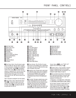
˘ ¯ AVR 325 ready LOGIC 7 VMAx FRONT-PANEL CONTROLS ˜ ı 25 Ò ˆ 26 Ú 1 3 5 7 2 46 8 9 !# )@ $ % & ( ^* Ô Ó 1 Main Power Switch 2 System Power Control 3 Power Indicator 4 Headphone Jack 5 Tone Mode 6 Speaker Selector 7 Surround Mode Group Selector 8 Surround Mode Selector 9 Tuning Selector ) ‹ Button ! Tuner Band Selector @ Set Button # › Button $ Preset Station Selector % Input Source Selector ^ Tuner Mode Selector & Optical 3 Digital Input * Coaxial 3 Digital Input ( Video 4 Video Input Jacks Ó Video 4 Audio Input Jacks Ô Bass Control Balance Control Ò Treble Control Ú Channel Adjust Selector Û Delay Adjust Selector Ù Digital Input Selector ı Volume Control ˆ Input Indicators ˜ Main Information Display ¯ Remote Sensor Window ˘ Surround Mode Indicators 1 Main Power Switch: Press this button to apply power to the AVR 325. When the switch is pressed in, the unit is placed in a Standby mode, as indicated by the amber Power Indicator 3 surrounding the System Power Control 2. This button MUST be pressed in to operate the unit. To turn the unit off and prevent the use of the remote control, this switch should be pressed until it pops out from the front panel so that the word "OFF" may be read at the top of the switch. NOTE: This switch is normally left in the "ON" position. 2 System Power Control: When the Main Power Switch 1 is "ON," press this button to turn on the AVR 325; press it again to turn the unit off. Note that the Power Indicator 3 surrounding the switch will turn green when the unit is on. 3 Power Indicator: This LED will be lit in amber when the unit is in the Standby mode to signal that the unit is ready to be turned on. When the unit is in operation, the indicator will turn green. 4 Headphone Jack: This jack may be used to listen to the AVR 325's output through a pair of headphones. Be certain that the headphones have a standard 1/4" stereo phone plug. The main room speakers will automatically be turned off when the headphone jack is in use. 5 Tone Mode: This button controls the tone control settings, enabling adjustment of the bass and treble boost/cut or the removal of the tone controls from the signal path. The first press of the button displays a TONE IN message in the Main Information Display ˜. If you wish to set the tone controls to "flat," without any treble or bass alteration, press the ‹ or › Selector Buttons )# so that TONE OUT appears in the Lower Display Line B. 6 Speaker Selector: Press this button to begin the process of configuring the AVR 325 for the type of speakers it is being used with. For information on configuring the speaker settings, see page 21. 7 Surround Mode Group Selector: Press this button to select the top-level group of surround modes. Each press of the button will select a major mode grouping in the following order: Dolby Modes _ DTS Digital Modes _ VMAx Modes _ DSP Modes _ Stereo Modes _ Logic 7 Modes Once the button is pressed so that the name of the desired surround mode group appears in the onscreen display and in the Lower Display Line B, press the Surround Mode Selector 8 to cycle through the individual modes available. For example, FRONT-PANEL CONTROLS 5
-
 1
1 -
 2
2 -
 3
3 -
 4
4 -
 5
5 -
 6
6 -
 7
7 -
 8
8 -
 9
9 -
 10
10 -
 11
11 -
12
-
13
-
14
-
15
-
16
-
17
-
18
-
19
-
20
-
21
-
22
-
23
-
24
-
25
-
26
-
27
-
28
-
29
-
30
-
31
-
32
-
33
-
34
-
35
-
36
-
37
-
38
-
39
-
40
-
41
-
42
-
43
-
44
-
45
-
46
-
47
-
48
-
49
-
50
-
51
-
52
-
53
-
54
-
55
-
56
 |
 |
