Harman Kardon AVR 325 Owners Manual - Page 8
Rear-panel Connections
 |
View all Harman Kardon AVR 325 manuals
Add to My Manuals
Save this manual to your list of manuals |
Page 8 highlights
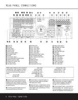
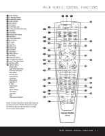
REAR-PANEL CONNECTIONS 41 39 37 35 33 31 j 42 40 38 36 34 32 k hf ig e d b ·‡fi c a°fl› AVR 325 ¶ • ª ¡ AM Antenna ™ FM Antenna £ Preamp Outputs ¢ Subwoofer Output ∞ A-BUS Connector § Surround Speaker Outputs ¶ Front Speaker Outputs • Fan Vents ª Center Speaker Outputs , Surround Back/Multiroom Speaker Outputs ⁄ Switched AC Accessory Outlet ¤ Unswitched AC Accessory Outlet ‹ AC Power Cord Jack › Video Monitor Outputs fi DVD Video Inputs fl Video 1 Video Inputs ‡ Video 1 Video Outputs ° Video 2 Video Inputs · Video 2 Video Outputs a Video 3 Video Inputs b Component Video Monitor Outputs c DVD Component Video Inputs d Video 2 Component Video Inputs e RS-232 Port f Multiroom IR Input g Remote IR Input h Remote IR Output i Coaxial Digital Audio Output , ⁄2 ‹ j Multiroom Audio Outputs k Optical Digital Audio Output 31 CD Audio Inputs 32 DVD Audio Inputs 33 Optical Digital Audio Inputs 34 Tape Inputs 35 Tape Outputs 36 Coaxial Digital Audio Inputs 37 Video 1 Audio Inputs 38 Video 1 Audio Outputs 39 Video 2 Audio Inputs 40 8-Channel Direct Inputs 41 Video 2 Audio Outputs 42 Video 3 Audio Inputs NOTE: To assist in making the correct connections for multichannel input, output and speaker connections, all connection jacks and terminals are color-coded in conformance with the latest CEA standards as follows: Front Left: White Front Right: Red Center: Green Surround Left: Blue Surround Right: Gray Surround Back Left: Brown Surround Back Right: Tan Subwoofer: Purple Digital Audio: Orange Composite Video: Yellow Component Video "Y": Green Component Video "Pr": Red Component Video "Pb": Blue ¡ AM Antenna: Connect the AM loop antenna supplied with the receiver to these terminals. If an external AM antenna is used, make connections to the AM and GND terminals in accordance with the instructions supplied with the antenna. ™ FM Antenna: Connect the supplied indoor (or an optional external) FM antenna to this terminal. £ Preamp Outputs: Connect these jacks to an optional, external power amplifier for applications where higher power is desired. ¢ Subwoofer Output: Connect this jack to the linelevel input of a powered subwoofer. If an external subwoofer amplifier is used, connect this jack to the subwoofer amplifier input. ∞ A-BUS Connector: Connect this jack to an optional A-BUS-certified remote room keypad or amplifier to extend the multiroom capabilities of your AVR 325. See page 34 for more information on A-BUS. § Surround Speaker Outputs: Connect these outputs to the matching + and - terminals on your surround channel speakers. In conformance with the new CEA color-code specification, the blue terminal is the 8 REAR-PANEL CONNECTIONS
-
 1
1 -
2
-
 3
3 -
 4
4 -
 5
5 -
 6
6 -
 7
7 -
 8
8 -
 9
9 -
 10
10 -
 11
11 -
 12
12 -
 13
13 -
14
-
15
-
16
-
17
-
18
-
19
-
20
-
21
-
22
-
23
-
24
-
25
-
26
-
27
-
28
-
29
-
30
-
31
-
32
-
33
-
34
-
35
-
36
-
37
-
38
-
39
-
40
-
41
-
42
-
43
-
44
-
45
-
46
-
47
-
48
-
49
-
50
-
51
-
52
-
53
-
54
-
55
-
56
 |
 |
