HealthRider H400 Treadmill English Manual - Page 9
Erly, The Console May Be Damaged When
 |
View all HealthRider H400 Treadmill manuals
Add to My Manuals
Save this manual to your list of manuals |
Page 9 highlights
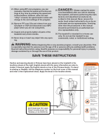
8. With the help of another person, hold the console assembly near the right Upright (96) and the left Upright (not shown). Connect the Wire Harness (118) to the wire harness in the console assembly. Make sure to connect the connectors properly (see the inset drawing); the connectors should slide together easily and snap into place. If the connectors do not slide together easily and snap into place, turn one connector and try again. IF THE CONNECTORS ARE NOT CONNECTED PROPERLY, THE CONSOLE MAY BE DAMAGED WHEN THE POWER IS TURNED ON. Insert the excess wire harness back into the right Handrail (108). Set the console assembly on the right Upright (96) and the left Upright (not shown). Thread two 1/4" x 1" Bolts (88) with 1/4" Star Washers (87) into each side of the console assembly. After you have started all four Bolts, tighten them. 8 Console Assembly 118 Right Handrail 108 118 87 88 96 9. Make sure that all parts are properly tightened before you use the treadmill. Note: Extra hardware may be included. Keep the included hex keys in a secure place. The large hex key is used to adjust the walking belt (see pages 26 and 27). To protect the floor or carpet, place a mat under the treadmill. If there is a sheet of clear plastic on a decal, remove the plastic. If you purchase the optional chest pulse sensor (see page 22), follow the steps below to install the receiver included with the chest pulse sensor. 1. Make sure that the power cord is unplugged. Remove the 3/4" Screw (33) and the Access Door (105) from the Console Back (104). 2. Connect the wire on the receiver (A) to the indicated wire extending from the Console Back (104). Remove the paper from the adhesive pad on the back of the receiver. Hold the receiver so the small cylinder is near the lower edge of the receiver and is facing the Console Back as shown. Firmly press the receiver onto the indicated corner of the Access Door (105). Note: If there are two screws included with the chest pulse sensor and two plastic posts on the inside of the Access Door, attach the receiver to the plastic posts on the Access Door with the two screws. Wire A Cylinder 104 105 33 3. Make sure that no wires are pinched. Reattach the Access Door (105) with the 3/4" Screw (33). The other wires included with the receiver may be discarded. 9
-
 1
1 -
2
-
3
-
 4
4 -
 5
5 -
 6
6 -
 7
7 -
 8
8 -
 9
9 -
 10
10 -
 11
11 -
 12
12 -
 13
13 -
 14
14 -
15
-
16
-
17
-
18
-
19
-
20
-
21
-
22
-
23
-
24
-
25
-
26
-
27
-
28
-
29
-
30
-
31
-
32
-
33
-
34
 |
 |
