HP 5600 TFT5600 Rackmount Keyboard and Monitor (RKM) User Guide - Page 47
Moving the TFT5600 RKM Installed in a Rack, top and bottom holes are aligned with the pins. - rail kit
 |
UPC - 720591607586
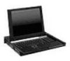
View all HP 5600 manuals
Add to My Manuals
Save this manual to your list of manuals |
Page 47 highlights
Care and Maintenance Moving the TFT5600 RKM Installed in a Rack When moving the TFT5600 RKM installed in a rack, it is recommended to install the lock plates, included in your kit, on each side of the unit and rack. To install the lock plates: 1. Fully extend the sliding rails until they lock. 2. Place the lock plate behind the corner of the front plastic bezel, making sure the top and bottom holes are aligned with the pins. 3. Insert one 6-32 screw (1) into the middle hole on the lock plate, securing it to the unit. 4. Insert one M-6 screw (2) to the other end of the lock plate, securing the unit to the rack. 5. Repeat steps 2 through 4 to install the other lock plate. 2 1 Figure 4-1: Installing lock plates HP TFT5600 Rackmount Keyboard and Monitor (RKM) 4-3
-
 1
1 -
2
-
3
-
4
-
5
-
6
-
7
-
8
-
9
-
10
-
11
-
12
-
13
-
14
-
15
-
16
-
17
-
18
-
19
-
20
-
21
-
22
-
23
-
24
-
25
-
26
-
27
-
28
-
29
-
30
-
31
-
32
-
33
-
34
-
35
-
36
-
37
-
38
-
39
-
40
-
41
-
 42
42 -
 43
43 -
 44
44 -
 45
45 -
 46
46 -
 47
47 -
 48
48 -
 49
49 -
 50
50 -
 51
51 -
 52
52 -
53
-
54
-
55
-
56
-
57
-
58
-
59
-
60
-
61
-
62
-
63
 |
 |
