HP Cisco MDS 9020 Cisco MDS 9200 Series Hardware Installation Guide (OL-16188- - Page 61
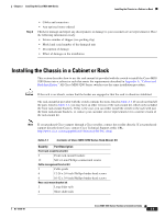
Installing the Chassis in a Cabinet or Rack
 |
View all HP Cisco MDS 9020 manuals
Add to My Manuals
Save this manual to your list of manuals |
Page 61 highlights
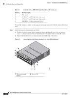
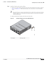
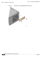
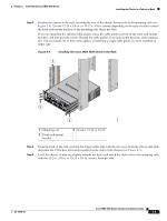
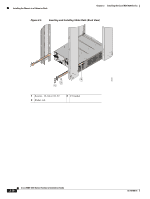
Chapter 2 Installing the Cisco MDS 9200 Series Installing the Chassis in a Cabinet or Rack Step 2 • Cables and connectors • Any optional items ordered Check for damage and report any discrepancies or damage to your customer service representative. Have the following information ready: • Invoice number of shipper (see packing slip) • Model and serial number of the damaged unit • Description of damage • Effect of damage on the installation Installing the Chassis in a Cabinet or Rack This section describes how to use the rack-mount kit provided with the switch to install the Cisco MDS 9200 Series into a cabinet or rack that meets the requirements described in Appendix A, "Cabinet and Rack Installation." All Cisco MDS 9200 Series switches use the same installation procedure. Caution If the rack is on wheels, ensure that the brakes are engaged or that the rack is otherwise stabilized. The rack-mount kit provided with the switch contains the items listed in Table 2-1. If you do not find all the parts listed in Table 2-1, you may have an older version of the rack-mount kit, which only included the front rack-mount brackets. If this is the case, you can either install the switch in the rack with just the front rack-mount brackets, or contact your customer service representative for a current version of the rack-mount kit. Note If you purchased Cisco support through a Cisco reseller, contact the reseller directly. If you purchased support directly from Cisco, contact Cisco Technical Support at this URL: http://www.cisco.com/warp/public/687/Directory/DirTAC.shtml Table 2-1 Contents of Cisco MDS 9200 Series Rack-Mount Kit Quantity Part Description Front rack-mount bracket kit 2 Front rack-mount brackets 12 M4 x 6-mm Phillips countersunk screws Cable management bracket kit 2 Cable guide 6 12-24 x 3/4-inch Phillips binder-head screws 6 10-32 x 3/4-inch Phillips binder-head screws Rear rack-mount bracket kit 2 Long slider rails 2 Short slider rails OL-16188-01 Cisco MDS 9200 Series Hardware Installation Guide 2-5
-
 1
1 -
2
-
3
-
4
-
5
-
6
-
7
-
8
-
9
-
10
-
11
-
12
-
13
-
14
-
15
-
16
-
17
-
18
-
19
-
20
-
21
-
22
-
23
-
24
-
25
-
26
-
27
-
28
-
29
-
30
-
31
-
32
-
33
-
34
-
35
-
36
-
37
-
38
-
39
-
40
-
41
-
42
-
43
-
44
-
45
-
46
-
47
-
48
-
49
-
50
-
51
-
52
-
53
-
54
-
55
-
 56
56 -
 57
57 -
 58
58 -
 59
59 -
 60
60 -
 61
61 -
 62
62 -
 63
63 -
 64
64 -
 65
65 -
 66
66 -
67
-
68
-
69
-
70
-
71
-
72
-
73
-
74
-
75
-
76
-
77
-
78
-
79
-
80
-
81
-
82
-
83
-
84
-
85
-
86
-
87
-
88
-
89
-
90
-
91
-
92
-
93
-
94
-
95
-
96
-
97
-
98
-
99
-
100
-
101
-
102
-
103
-
104
-
105
-
106
-
107
-
108
-
109
-
110
-
111
-
112
-
113
-
114
-
115
-
116
-
117
-
118
-
119
-
120
-
121
-
122
-
123
-
124
-
125
-
126
-
127
-
128
-
129
-
130
-
131
-
132
-
133
-
134
-
135
-
136
-
137
-
138
-
139
-
140
-
141
-
142
-
143
-
144
-
145
-
146
-
147
-
148
-
149
-
150
-
151
-
152
-
153
-
154
-
155
-
156
-
157
-
158
-
159
-
160
-
161
-
162
-
163
-
164
 |
 |
