HP Cisco MDS 9020 Cisco MDS 9200 Series Hardware Installation Guide (OL-16188- - Page 95
Removing a Fan Module, Installing a Fan Module, When removing the fan tray
 |
View all HP Cisco MDS 9020 manuals
Add to My Manuals
Save this manual to your list of manuals |
Page 95 highlights
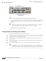
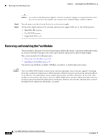
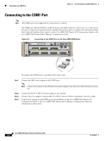
Chapter 2 Installing the Cisco MDS 9200 Series Removing and Installing Components Figure 2-23 shows a fan module partially installed in the Cisco MDS 9200 Series. Figure 2-23 Fan Module MDS 9216i 1 2 3 4 5 6 7 8 9 1 2 3 4 5 6 7 8 10 11 12 13 14 GE1 LINK- GE2 LINK- 9 10 11 12 13 14 15 16 122002 Removing a Fan Module Warning When removing the fan tray, keep your hands and fingers away from the spinning fan blades. Let the fan blades completely stop before you remove the fan tray. Statement 258 To remove a fan module, follow these steps: Step 1 Step 2 Step 3 Loosen the two captive screws on the fan module by turning them counterclockwise, using a flat-blade or number 2 Phillips screwdriver if required. Grasp the fan module with both hands and pull it outward; rock it gently, if necessary, to unseat the power connector from the backplane. Pull the fan module clear of the chassis. Caution If the switch is powered on, you must hot-swap another fan module into this switch within five minutes. Installing a Fan Module To install a fan module, follow these steps: Step 1 Step 2 Hold the fan module with the Fan Status LED at the top (see Figure 2-23). Place the fan module into the front chassis cavity so it rests on the chassis, lift the fan module up slightly to align the top and bottom chassis guides, then push the fan module into the chassis until it seats in the backplane and the captive screws make contact with the chassis, and tighten the captive screws. OL-16188-01 Cisco MDS 9200 Series Hardware Installation Guide 2-39
-
 1
1 -
2
-
3
-
4
-
5
-
6
-
7
-
8
-
9
-
10
-
11
-
12
-
13
-
14
-
15
-
16
-
17
-
18
-
19
-
20
-
21
-
22
-
23
-
24
-
25
-
26
-
27
-
28
-
29
-
30
-
31
-
32
-
33
-
34
-
35
-
36
-
37
-
38
-
39
-
40
-
41
-
42
-
43
-
44
-
45
-
46
-
47
-
48
-
49
-
50
-
51
-
52
-
53
-
54
-
55
-
56
-
57
-
58
-
59
-
60
-
61
-
62
-
63
-
64
-
65
-
66
-
67
-
68
-
69
-
70
-
71
-
72
-
73
-
74
-
75
-
76
-
77
-
78
-
79
-
80
-
81
-
82
-
83
-
84
-
85
-
86
-
87
-
88
-
89
-
 90
90 -
 91
91 -
 92
92 -
 93
93 -
 94
94 -
 95
95 -
 96
96 -
 97
97 -
 98
98 -
 99
99 -
 100
100 -
101
-
102
-
103
-
104
-
105
-
106
-
107
-
108
-
109
-
110
-
111
-
112
-
113
-
114
-
115
-
116
-
117
-
118
-
119
-
120
-
121
-
122
-
123
-
124
-
125
-
126
-
127
-
128
-
129
-
130
-
131
-
132
-
133
-
134
-
135
-
136
-
137
-
138
-
139
-
140
-
141
-
142
-
143
-
144
-
145
-
146
-
147
-
148
-
149
-
150
-
151
-
152
-
153
-
154
-
155
-
156
-
157
-
158
-
159
-
160
-
161
-
162
-
163
-
164
 |
 |
