HP Cisco MDS 9020 Cisco MDS 9200 Series Hardware Installation Guide (OL-16188- - Page 62
Quantity, Part Description,
 |
View all HP Cisco MDS 9020 manuals
Add to My Manuals
Save this manual to your list of manuals |
Page 62 highlights
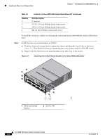
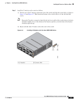
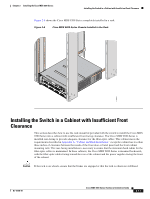
Installing the Chassis in a Cabinet or Rack Chapter 2 Installing the Cisco MDS 9200 Series Table 2-1 Quantity 2 6 6 4 Contents of Cisco MDS 9200 Series Rack-Mount Kit (continued) Part Description C brackets 12-24 x 3/4-inch Phillips binder-head screws 10-32 x 3/4-inch Phillips binder-head screws M4 x 6-mm, Phillips countersunk screws To install the switch in a cabinet or rack using the rack-mount kit provided with the switch, follow these steps: Step 1 Install the front rack-mount brackets as follows: a. Position a front rack-mount bracket against the chassis and align the screw holes as shown in Figure 2-1. Then attach the front rack-mount bracket to the chassis with six of the M4 screws. b. Repeat with the other front rack-mount bracket on the other side of the switch. Figure 2-1 Attaching Front Rack-Mount Bracket to the Cisco MDS 9200 Series 1 2 MDS 9216i 3 4 5 6 7 8 9 10 11 12 13 14 LINK GE1 LINK GE2 1 Front rack-mount bracket 12 2 Screws, M4 116891 Cisco MDS 9200 Series Hardware Installation Guide 2-6 OL-16188-01
-
 1
1 -
2
-
3
-
4
-
5
-
6
-
7
-
8
-
9
-
10
-
11
-
12
-
13
-
14
-
15
-
16
-
17
-
18
-
19
-
20
-
21
-
22
-
23
-
24
-
25
-
26
-
27
-
28
-
29
-
30
-
31
-
32
-
33
-
34
-
35
-
36
-
37
-
38
-
39
-
40
-
41
-
42
-
43
-
44
-
45
-
46
-
47
-
48
-
49
-
50
-
51
-
52
-
53
-
54
-
55
-
56
-
 57
57 -
 58
58 -
 59
59 -
 60
60 -
 61
61 -
 62
62 -
 63
63 -
 64
64 -
 65
65 -
 66
66 -
 67
67 -
68
-
69
-
70
-
71
-
72
-
73
-
74
-
75
-
76
-
77
-
78
-
79
-
80
-
81
-
82
-
83
-
84
-
85
-
86
-
87
-
88
-
89
-
90
-
91
-
92
-
93
-
94
-
95
-
96
-
97
-
98
-
99
-
100
-
101
-
102
-
103
-
104
-
105
-
106
-
107
-
108
-
109
-
110
-
111
-
112
-
113
-
114
-
115
-
116
-
117
-
118
-
119
-
120
-
121
-
122
-
123
-
124
-
125
-
126
-
127
-
128
-
129
-
130
-
131
-
132
-
133
-
134
-
135
-
136
-
137
-
138
-
139
-
140
-
141
-
142
-
143
-
144
-
145
-
146
-
147
-
148
-
149
-
150
-
151
-
152
-
153
-
154
-
155
-
156
-
157
-
158
-
159
-
160
-
161
-
162
-
163
-
164
 |
 |
