HP Cisco MDS 9020 Cisco MDS 9200 Series Hardware Installation Guide (OL-16188- - Page 78
Attaching the ESD Wrist Strap to the System Ground Lug Screw
 |
View all HP Cisco MDS 9020 manuals
Add to My Manuals
Save this manual to your list of manuals |
Page 78 highlights
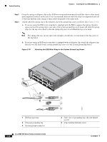
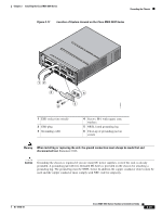
System Grounding Chapter 2 Installing the Cisco MDS 9200 Series Step 2 Step 3 Grasp the spring or alligator clip on the ESD wrist strap and momentarily touch the clip to a bare metal spot (unpainted surface) on the rack. Cisco recommends that you touch the clip to an unpainted rack rail so that any built-up static charge is then safely dissipated to the entire rack. Attach either the spring clip or the alligator clip to the ground lug screw as follows (See Figure 2-16.): a. If you are using the ESD wrist strap that is supplied with the FRUs, squeeze the spring clip jaws open, position the spring clip to one side of the system ground lug screw head, and slide the spring clip over the lug screw head so that the spring clip jaws close behind the lug screw head. Note The spring clip jaws do not open wide enough to fit directly over the head of the lug screw or the lug barrel. b. If you are using an ESD wrist strap that is equipped with an alligator clip, attach the alligator clip directly over the head of the system ground lug screw or to the system ground lug barrel. Figure 2-16 Attaching the ESD Wrist Strap to the System Ground Lug Screw 5 1 2 MDS 9216i 3 4 5 6 7 8 9 10 11 12 13 14 LINK GE1 LINK GE2 1 1 ESD ground strap 2 Clip and grounding lug 5 System ground connector 2-22 Cisco MDS 9200 Series Hardware Installation Guide 2 3 4 3 Side view of grounding lug (clip slid behind screw) 4 Clip installed (behind screw) OL-16188-01 154017
-
 1
1 -
2
-
3
-
4
-
5
-
6
-
7
-
8
-
9
-
10
-
11
-
12
-
13
-
14
-
15
-
16
-
17
-
18
-
19
-
20
-
21
-
22
-
23
-
24
-
25
-
26
-
27
-
28
-
29
-
30
-
31
-
32
-
33
-
34
-
35
-
36
-
37
-
38
-
39
-
40
-
41
-
42
-
43
-
44
-
45
-
46
-
47
-
48
-
49
-
50
-
51
-
52
-
53
-
54
-
55
-
56
-
57
-
58
-
59
-
60
-
61
-
62
-
63
-
64
-
65
-
66
-
67
-
68
-
69
-
70
-
71
-
72
-
 73
73 -
 74
74 -
 75
75 -
 76
76 -
 77
77 -
 78
78 -
 79
79 -
 80
80 -
 81
81 -
 82
82 -
 83
83 -
84
-
85
-
86
-
87
-
88
-
89
-
90
-
91
-
92
-
93
-
94
-
95
-
96
-
97
-
98
-
99
-
100
-
101
-
102
-
103
-
104
-
105
-
106
-
107
-
108
-
109
-
110
-
111
-
112
-
113
-
114
-
115
-
116
-
117
-
118
-
119
-
120
-
121
-
122
-
123
-
124
-
125
-
126
-
127
-
128
-
129
-
130
-
131
-
132
-
133
-
134
-
135
-
136
-
137
-
138
-
139
-
140
-
141
-
142
-
143
-
144
-
145
-
146
-
147
-
148
-
149
-
150
-
151
-
152
-
153
-
154
-
155
-
156
-
157
-
158
-
159
-
160
-
161
-
162
-
163
-
164
 |
 |
