HP Cisco MDS 9216A Cisco MDS 9500 Series Hardware Installation Guide (OL-17467 - Page 119
Removing Supervisor Modules
 |
View all HP Cisco MDS 9216A manuals
Add to My Manuals
Save this manual to your list of manuals |
Page 119 highlights
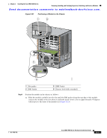
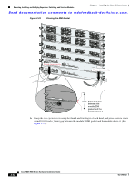
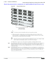
Chapter 2 Installing the Cisco MDS 9500 Series Removing, Installing, and Verifying Supervisor, Switching, and Services Modules Send documentation comments to [email protected]. Caution To prevent ESD damage, wear grounding wrist straps during these procedures and handle modules by the carrier edges only. Note Install the Cisco MDS 9500 Series chassis in the rack before installing modules. See the "Installing the Chassis in a Cabinet or Rack" section on page 2-6. Note In systems with redundant supervisor modules, you can replace the faulty supervisor while the system is operating, provided that one supervisor is always operating. Removing Supervisor Modules To remove a Supervisor-1 or Supervisor-2 module from the chassis, follow these steps: Step 1 Step 2 Step 3 Step 4 Step 5 Step 6 Step 7 Step 8 Shut down the crossbar switching fabric functionality in the supervisor module of the Cisco MDS 9509 and 9506 Directors by using the out-of-service module slot command (where slot refers to the slot number for the Supervisor-1 or Supervisor-2 module where the integrated crossbar is located). Upload the current configuration to a server if the switch has only one supervisor module. For information about the correct command, see the Cisco MDS 9000 Family CLI Configuration Guide. Fail over to the standby supervisor if the switch has two supervisor modules and the supervisor you are removing is currently active. For information on how to fail over a supervisor module, see the Cisco MDS 9000 Family CLI Configuration Guide. Disconnect any network interface cables attached to the module. Loosen the two captive screws on the module being removed. Remove the module from the chassis as follows: a. Place your thumbs on the left and right ejector levers and simultaneously rotate the levers outward to unseat the module from the backplane connector. b. Grasp the front edge of the module and slide the module partially out of the slot. Place your other hand under the module to support the weight of the module. Do not touch the module circuitry. Place the module on an antistatic mat or antistatic foam, or immediately reinstall it in another slot. Install a filler panel on an empty slot to keep the chassis dust-free and to maintain proper airflow through the chassis. Warning Blank faceplates and cover panels serve three important functions: they prevent exposure to hazardous voltages and currents inside the chassis; they contain electromagnetic interference (EMI) that might disrupt other equipment; and they direct the flow of cooling air through the chassis. Do not operate the system unless all cards, faceplates, front covers, and rear covers are in place. Statement 1029 OL-17467-02 Cisco MDS 9500 Series Hardware Installation Guide 2-39
-
 1
1 -
2
-
3
-
4
-
5
-
6
-
7
-
8
-
9
-
10
-
11
-
12
-
13
-
14
-
15
-
16
-
17
-
18
-
19
-
20
-
21
-
22
-
23
-
24
-
25
-
26
-
27
-
28
-
29
-
30
-
31
-
32
-
33
-
34
-
35
-
36
-
37
-
38
-
39
-
40
-
41
-
42
-
43
-
44
-
45
-
46
-
47
-
48
-
49
-
50
-
51
-
52
-
53
-
54
-
55
-
56
-
57
-
58
-
59
-
60
-
61
-
62
-
63
-
64
-
65
-
66
-
67
-
68
-
69
-
70
-
71
-
72
-
73
-
74
-
75
-
76
-
77
-
78
-
79
-
80
-
81
-
82
-
83
-
84
-
85
-
86
-
87
-
88
-
89
-
90
-
91
-
92
-
93
-
94
-
95
-
96
-
97
-
98
-
99
-
100
-
101
-
102
-
103
-
104
-
105
-
106
-
107
-
108
-
109
-
110
-
111
-
112
-
113
-
 114
114 -
 115
115 -
 116
116 -
 117
117 -
 118
118 -
 119
119 -
 120
120 -
 121
121 -
 122
122 -
 123
123 -
 124
124 -
125
-
126
-
127
-
128
-
129
-
130
-
131
-
132
-
133
-
134
-
135
-
136
-
137
-
138
-
139
-
140
-
141
-
142
-
143
-
144
-
145
-
146
-
147
-
148
-
149
-
150
-
151
-
152
-
153
-
154
-
155
-
156
-
157
-
158
-
159
-
160
-
161
-
162
-
163
-
164
-
165
-
166
-
167
-
168
-
169
-
170
-
171
-
172
-
173
-
174
-
175
-
176
-
177
-
178
-
179
-
180
-
181
-
182
-
183
-
184
-
185
-
186
-
187
-
188
-
189
-
190
-
191
-
192
-
193
-
194
-
195
-
196
-
197
-
198
-
199
-
200
-
201
-
202
-
203
-
204
-
205
-
206
-
207
-
208
-
209
-
210
-
211
-
212
-
213
-
214
-
215
-
216
-
217
-
218
-
219
-
220
-
221
-
222
-
223
-
224
-
225
-
226
-
227
-
228
-
229
-
230
-
231
-
232
-
233
-
234
-
235
-
236
-
237
-
238
-
239
-
240
-
241
-
242
-
243
-
244
-
245
-
246
-
247
-
248
-
249
-
250
-
251
-
252
-
253
-
254
-
255
-
256
-
257
-
258
-
259
-
260
-
261
-
262
-
263
-
264
-
265
-
266
-
267
-
268
-
269
-
270
-
271
-
272
-
273
-
274
-
275
-
276
-
277
-
278
-
279
-
280
-
281
-
282
-
283
-
284
-
285
-
286
-
287
-
288
 |
 |
