HP Cisco MDS 9216A Cisco MDS 9500 Series Hardware Installation Guide (OL-17467 - Page 159
Installing a Clock Module into the Cisco MDS 9513 Director
 |
View all HP Cisco MDS 9216A manuals
Add to My Manuals
Save this manual to your list of manuals |
Page 159 highlights
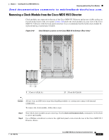
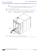
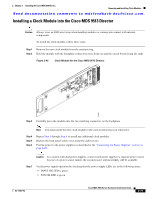
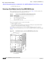
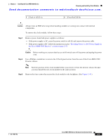
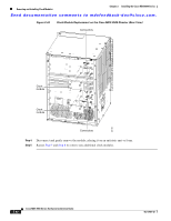
Chapter 2 Installing the Cisco MDS 9500 Series Removing and Installing Clock Modules Send documentation comments to [email protected]. Installing a Clock Module into the Cisco MDS 9513 Director Caution Always wear an ESD wrist strap when handling modules or coming into contact with internal components. To install the clock module, follow these steps: Step 1 Remove the new clock module from the antistatic bag. Step 2 Hold the module with the backplane connectors away from you and the circuit board facing the right. Figure 2-42 Clock Module for the Cisco MDS 9513 Director 147965 Step 3 Carefully press the module onto the two matching connectors on the backplane. Note You must install the new clock module in the same position that you removed it. Step 4 Step 5 Step 6 Repeat Step 1 through Step 4 to install any additional clock modules. Replace the back panel safety cover using the eight screws. Provide power to the power supplies as described in the "Connecting the Power Supplies" section on page 2-28. Caution In a system with dual power supplies, connect each power supply to a separate power source. In case of a power source failure, the second source will most likely still be available. Step 7 Verify power supply operation by checking that the power supply LEDs are in the following states: • INPUT OK LED is green. • FAN OK LED is green. OL-17467-02 Cisco MDS 9500 Series Hardware Installation Guide 2-79
-
 1
1 -
2
-
3
-
4
-
5
-
6
-
7
-
8
-
9
-
10
-
11
-
12
-
13
-
14
-
15
-
16
-
17
-
18
-
19
-
20
-
21
-
22
-
23
-
24
-
25
-
26
-
27
-
28
-
29
-
30
-
31
-
32
-
33
-
34
-
35
-
36
-
37
-
38
-
39
-
40
-
41
-
42
-
43
-
44
-
45
-
46
-
47
-
48
-
49
-
50
-
51
-
52
-
53
-
54
-
55
-
56
-
57
-
58
-
59
-
60
-
61
-
62
-
63
-
64
-
65
-
66
-
67
-
68
-
69
-
70
-
71
-
72
-
73
-
74
-
75
-
76
-
77
-
78
-
79
-
80
-
81
-
82
-
83
-
84
-
85
-
86
-
87
-
88
-
89
-
90
-
91
-
92
-
93
-
94
-
95
-
96
-
97
-
98
-
99
-
100
-
101
-
102
-
103
-
104
-
105
-
106
-
107
-
108
-
109
-
110
-
111
-
112
-
113
-
114
-
115
-
116
-
117
-
118
-
119
-
120
-
121
-
122
-
123
-
124
-
125
-
126
-
127
-
128
-
129
-
130
-
131
-
132
-
133
-
134
-
135
-
136
-
137
-
138
-
139
-
140
-
141
-
142
-
143
-
144
-
145
-
146
-
147
-
148
-
149
-
150
-
151
-
152
-
153
-
 154
154 -
 155
155 -
 156
156 -
 157
157 -
 158
158 -
 159
159 -
 160
160 -
 161
161 -
 162
162 -
 163
163 -
 164
164 -
165
-
166
-
167
-
168
-
169
-
170
-
171
-
172
-
173
-
174
-
175
-
176
-
177
-
178
-
179
-
180
-
181
-
182
-
183
-
184
-
185
-
186
-
187
-
188
-
189
-
190
-
191
-
192
-
193
-
194
-
195
-
196
-
197
-
198
-
199
-
200
-
201
-
202
-
203
-
204
-
205
-
206
-
207
-
208
-
209
-
210
-
211
-
212
-
213
-
214
-
215
-
216
-
217
-
218
-
219
-
220
-
221
-
222
-
223
-
224
-
225
-
226
-
227
-
228
-
229
-
230
-
231
-
232
-
233
-
234
-
235
-
236
-
237
-
238
-
239
-
240
-
241
-
242
-
243
-
244
-
245
-
246
-
247
-
248
-
249
-
250
-
251
-
252
-
253
-
254
-
255
-
256
-
257
-
258
-
259
-
260
-
261
-
262
-
263
-
264
-
265
-
266
-
267
-
268
-
269
-
270
-
271
-
272
-
273
-
274
-
275
-
276
-
277
-
278
-
279
-
280
-
281
-
282
-
283
-
284
-
285
-
286
-
287
-
288
 |
 |
