HP Cisco MDS 9216i Cisco MDS 9500 Series Hardware Installation Guide (OL-17467 - Page 144
Removing and Installing the PEMs on the Cisco MDS 9506 Director, Removing an AC PEM
 |
View all HP Cisco MDS 9216i manuals
Add to My Manuals
Save this manual to your list of manuals |
Page 144 highlights
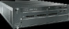
Removing and Installing a Power Supply or PEM Chapter 2 Installing the Cisco MDS 9500 Series Send documentation comments to [email protected]. Removing and Installing the PEMs on the Cisco MDS 9506 Director Note For instructions on connecting the cables to the PEMs, see the "Connecting the Power Supplies" section on page 2-28. The Cisco MDS 9506 Director uses PEMs to provide an input power connection on the front of the chassis. In addition, the PEM provides current protection, surge and EMI suppression, and filtering functions. An AC PEM is required for each AC power supply, and a DC PEM for each DC power supply. The PEM that is on the left when viewed from the front of the switch (PEM 1) connects the site power source to power supply 1 (upper power supply); the PEM on the right (PEM 2) connects the site power source to power supply 2 (lower power supply). Note You need a flat-blade or number 2 Phillips-head screwdriver to perform these procedures. Removing an AC PEM To remove an AC PEM from a Cisco MDS 9506 chassis, follow these steps: Step 1 Step 2 Step 3 Remove power from the PEM by pressing the power switch to off (0). Loosen the captive screws and pull the PEM of the chassis, supporting the PEM from underneath. If the PEM bay is to remain empty, install a filler panel over the opening and tighten the captive screws to 8 in-lb. Removing a DC PEM Warning Before performing any of the following procedures, ensure that power is removed from the DC circuit. Statement 1003 To remove a DC PEM from a Cisco MDS 9506 chassis, follow these steps: Step 1 Step 2 Step 3 Ensure that all power is off by locating the circuit breaker on the panel board that services the DC circuit. Switch the circuit breaker to the off position, and tape the switch handle of the circuit breaker in the off position. Loosen the captive screws and pull the DC PEM from the chassis, holding it by the edges. Remove the cables from the DC PEM by removing the terminal block screws, and then removing the ring lugs from the screws. See Figure 2-35 for the location of the terminal block screws. 2-64 Cisco MDS 9500 Series Hardware Installation Guide OL-17467-02
-
 1
1 -
2
-
3
-
4
-
5
-
6
-
7
-
8
-
9
-
10
-
11
-
12
-
13
-
14
-
15
-
16
-
17
-
18
-
19
-
20
-
21
-
22
-
23
-
24
-
25
-
26
-
27
-
28
-
29
-
30
-
31
-
32
-
33
-
34
-
35
-
36
-
37
-
38
-
39
-
40
-
41
-
42
-
43
-
44
-
45
-
46
-
47
-
48
-
49
-
50
-
51
-
52
-
53
-
54
-
55
-
56
-
57
-
58
-
59
-
60
-
61
-
62
-
63
-
64
-
65
-
66
-
67
-
68
-
69
-
70
-
71
-
72
-
73
-
74
-
75
-
76
-
77
-
78
-
79
-
80
-
81
-
82
-
83
-
84
-
85
-
86
-
87
-
88
-
89
-
90
-
91
-
92
-
93
-
94
-
95
-
96
-
97
-
98
-
99
-
100
-
101
-
102
-
103
-
104
-
105
-
106
-
107
-
108
-
109
-
110
-
111
-
112
-
113
-
114
-
115
-
116
-
117
-
118
-
119
-
120
-
121
-
122
-
123
-
124
-
125
-
126
-
127
-
128
-
129
-
130
-
131
-
132
-
133
-
134
-
135
-
136
-
137
-
138
-
 139
139 -
 140
140 -
 141
141 -
 142
142 -
 143
143 -
 144
144 -
 145
145 -
 146
146 -
 147
147 -
 148
148 -
 149
149 -
150
-
151
-
152
-
153
-
154
-
155
-
156
-
157
-
158
-
159
-
160
-
161
-
162
-
163
-
164
-
165
-
166
-
167
-
168
-
169
-
170
-
171
-
172
-
173
-
174
-
175
-
176
-
177
-
178
-
179
-
180
-
181
-
182
-
183
-
184
-
185
-
186
-
187
-
188
-
189
-
190
-
191
-
192
-
193
-
194
-
195
-
196
-
197
-
198
-
199
-
200
-
201
-
202
-
203
-
204
-
205
-
206
-
207
-
208
-
209
-
210
-
211
-
212
-
213
-
214
-
215
-
216
-
217
-
218
-
219
-
220
-
221
-
222
-
223
-
224
-
225
-
226
-
227
-
228
-
229
-
230
-
231
-
232
-
233
-
234
-
235
-
236
-
237
-
238
-
239
-
240
-
241
-
242
-
243
-
244
-
245
-
246
-
247
-
248
-
249
-
250
-
251
-
252
-
253
-
254
-
255
-
256
-
257
-
258
-
259
-
260
-
261
-
262
-
263
-
264
-
265
-
266
-
267
-
268
-
269
-
270
-
271
-
272
-
273
-
274
-
275
-
276
-
277
-
278
-
279
-
280
-
281
-
282
-
283
-
284
-
285
-
286
-
287
-
288
 |
 |
