HP Cisco MDS 9222i Cisco MDS 9500 Series Hardware Installation Guide (OL-17467 - Page 108
Starting Up the Switch, Connecting the Power Supplies
 |
View all HP Cisco MDS 9222i manuals
Add to My Manuals
Save this manual to your list of manuals |
Page 108 highlights
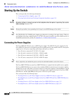
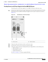
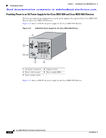
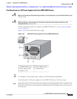
Starting Up the Switch Chapter 2 Installing the Cisco MDS 9500 Series Send documentation comments to [email protected]. Starting Up the Switch This section provides the following information: • Connecting the Power Supplies, page 2-28 • Powering Up the Switch and Verifying Component Installation, page 2-36 Warning Hazardous voltage or energy is present on the backplane when the system is operating. Use caution when servicing. Statement 1034 Caution During this procedure, wear grounding wrist straps to avoid ESD damage to the switch. Note The 2500-W (DS-CAC-2500W) power supplies provide power according to the input voltage. If they are in redundant rather than combined mode at 110 VAC, they may be unable to provide adequate power to all modules present in the system. See Appendix D, "Technical Specifications." Connecting the Power Supplies The Cisco MDS 9513 Director uses a 6000-W power supply. The 6000-W AC power supplies for the Cisco MDS 9513 Director are designed to provide an output power for the modules and fans. Each power supply has two AC power connections and will provide power as follows: • One AC power connection @110 VAC = No output • Two AC power connection @110 VAC = 2900-W output • One AC power connection @ 220 VAC = 2900-W output • Two AC power connection @ 220 VAC = 6000-W output Note Power output does not include the power used by the individual modules used in the chassis. The Cisco MDS 9509 Director and Cisco MDS 9506 Director support both AC and DC power supplies. The Cisco MDS 9506 Director uses power entry modules (PEMs) to provide power to its power supplies, whether they are AC or DC (there is no power connector on the power supplies). The left PEM (as viewed from the front of the switch) provides power to the upper power supply in the back of the Cisco MDS 9506 Director, and the right PEM provides power to the lower power supply. This section provides the following topics: • Providing Power to an AC Power Supply for the Cisco MDS 9513 Director, page 2-29 • Providing Power to an AC Power Supply for the Cisco MDS 9509 and Cisco MDS 9506 Directors, page 2-30 • Providing Power to a DC Power Supply in the Cisco MDS 9509 Director, page 2-33 • Providing Power to a DC Power Supply in the Cisco MDS 9506 Director, page 2-34 2-28 Cisco MDS 9500 Series Hardware Installation Guide OL-17467-02
-
 1
1 -
2
-
3
-
4
-
5
-
6
-
7
-
8
-
9
-
10
-
11
-
12
-
13
-
14
-
15
-
16
-
17
-
18
-
19
-
20
-
21
-
22
-
23
-
24
-
25
-
26
-
27
-
28
-
29
-
30
-
31
-
32
-
33
-
34
-
35
-
36
-
37
-
38
-
39
-
40
-
41
-
42
-
43
-
44
-
45
-
46
-
47
-
48
-
49
-
50
-
51
-
52
-
53
-
54
-
55
-
56
-
57
-
58
-
59
-
60
-
61
-
62
-
63
-
64
-
65
-
66
-
67
-
68
-
69
-
70
-
71
-
72
-
73
-
74
-
75
-
76
-
77
-
78
-
79
-
80
-
81
-
82
-
83
-
84
-
85
-
86
-
87
-
88
-
89
-
90
-
91
-
92
-
93
-
94
-
95
-
96
-
97
-
98
-
99
-
100
-
101
-
102
-
 103
103 -
 104
104 -
 105
105 -
 106
106 -
 107
107 -
 108
108 -
 109
109 -
 110
110 -
 111
111 -
 112
112 -
 113
113 -
114
-
115
-
116
-
117
-
118
-
119
-
120
-
121
-
122
-
123
-
124
-
125
-
126
-
127
-
128
-
129
-
130
-
131
-
132
-
133
-
134
-
135
-
136
-
137
-
138
-
139
-
140
-
141
-
142
-
143
-
144
-
145
-
146
-
147
-
148
-
149
-
150
-
151
-
152
-
153
-
154
-
155
-
156
-
157
-
158
-
159
-
160
-
161
-
162
-
163
-
164
-
165
-
166
-
167
-
168
-
169
-
170
-
171
-
172
-
173
-
174
-
175
-
176
-
177
-
178
-
179
-
180
-
181
-
182
-
183
-
184
-
185
-
186
-
187
-
188
-
189
-
190
-
191
-
192
-
193
-
194
-
195
-
196
-
197
-
198
-
199
-
200
-
201
-
202
-
203
-
204
-
205
-
206
-
207
-
208
-
209
-
210
-
211
-
212
-
213
-
214
-
215
-
216
-
217
-
218
-
219
-
220
-
221
-
222
-
223
-
224
-
225
-
226
-
227
-
228
-
229
-
230
-
231
-
232
-
233
-
234
-
235
-
236
-
237
-
238
-
239
-
240
-
241
-
242
-
243
-
244
-
245
-
246
-
247
-
248
-
249
-
250
-
251
-
252
-
253
-
254
-
255
-
256
-
257
-
258
-
259
-
260
-
261
-
262
-
263
-
264
-
265
-
266
-
267
-
268
-
269
-
270
-
271
-
272
-
273
-
274
-
275
-
276
-
277
-
278
-
279
-
280
-
281
-
282
-
283
-
284
-
285
-
286
-
287
-
288
 |
 |
