HP DL360 hp ProLiant DL360 generation 3 server high-density deployment - Page 17
To use the Rack/Site, Installation, Preparation Utility
 |
UPC - 613326948835
View all HP DL360 manuals
Add to My Manuals
Save this manual to your list of manuals |
Page 17 highlights
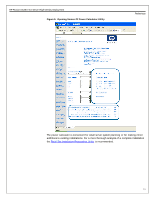
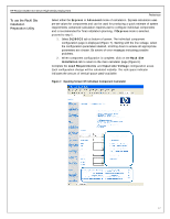
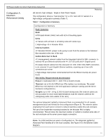
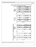
HP ProLiant DL360 G3 Server High-Density Deployment Preliminary To use the Rack/Site Installation Preparation Utility Select either the Express or Advanced mode of calculation. Express calculation uses pre-set values for components and can be used for producing a quick estimate of system requirements. Advanced calculation requires user to configure individual components and is recommended for final installation planning. If Express mode is selected, proceed to step 5. 1. Select DL360G3 tab at bottom of screen. The individual component configuration page is displayed (Figure 7). Starting with the line voltage, select the configuration parameters desired, scrolling down to ensure all appropriate parameters are chosen. Be aware of error messages indicating possible problems. 2. When component configuration is complete, click on the Rack Site Installation tab to return to the main calculator page (Figure 6). Complete the Load Requirements and Input Line Voltage configuration areas. Each configuration change will be calculated instantly. The rack space indicator indicates the amount of vertical space used/available. Figure 7. Opening Screen Of Individual Component Calculator 17
-
 1
1 -
2
-
3
-
4
-
5
-
6
-
7
-
8
-
9
-
10
-
11
-
 12
12 -
 13
13 -
 14
14 -
 15
15 -
 16
16 -
 17
17 -
 18
18 -
 19
19 -
 20
20 -
 21
21 -
 22
22 -
23
-
24
-
25
-
26
-
27
-
28
-
29
-
30
-
31
-
32
 |
 |
