HP DL360 hp ProLiant DL360 generation 3 server high-density deployment - Page 20
Configuration A Maximum Performance Density Power Cabling Diagram
 |
UPC - 613326948835
View all HP DL360 manuals
Add to My Manuals
Save this manual to your list of manuals |
Page 20 highlights
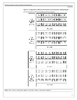
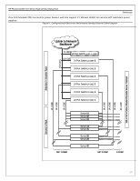
HP ProLiant DL360 G3 Server High-Density Deployment Preliminary Figure 8. Configuration A (Maximum Performance Density) Power Cabling Diagram (42 ProLiant DL360 G3 Servers with Redundant Power Supplies) Note: S1A= server 1 with power supply A and S1B= Server 1 with power supply B 20
-
 1
1 -
2
-
3
-
4
-
5
-
6
-
7
-
8
-
9
-
10
-
11
-
12
-
13
-
14
-
 15
15 -
 16
16 -
 17
17 -
 18
18 -
 19
19 -
 20
20 -
 21
21 -
 22
22 -
 23
23 -
 24
24 -
 25
25 -
26
-
27
-
28
-
29
-
30
-
31
-
32
 |
 |

HP ProLiant DL360 G3 Server High-Density Deployment
Preliminary
20
Figure 8.
Configuration A (Maximum Performance Density) Power Cabling Diagram
(42 ProLiant DL360 G3 Servers with Redundant Power Supplies)
Note:
S1A= server 1 with power supply A and S1B= Server 1 with power supply B