HP Dv7-2170us HP Pavilion dv7 Entertainment PC - Maintenance and Service Guide - Page 101
Processor, USB board see
 |
UPC - 884962256558
View all HP Dv7-2170us manuals
Add to My Manuals
Save this manual to your list of manuals |
Page 101 highlights
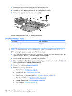
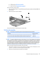
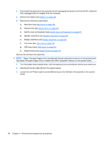
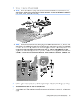
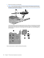
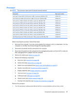
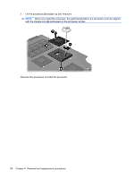
Processor NOTE: The processor spare part kit includes thermal material. Description Intel Core™2 Quad Q9100 2.26-GHz with 12-MB L2 cache and 1066-MHz FSB Intel Core2 Quad Q9000 2.00-GHz with 12-MB L2 cache and 1066-MHz FSB Intel Core2 Duo T9800 2.93-GHz with 6-MB L2 cache and 1066-MHz FSB Intel Core2 Duo T9550 2.66-GHz with 6-MB L2 cache and 1066-MHz FSB Intel Core2 Duo P8700 2.53-GHz with 3-MB L2 cache and 1066-MHz FSB Intel Core2 Duo P8600 2.40-GHz with 3-MB L2 cache and 1066-MHz FSB Intel Core2 Duo P7450 2.13-GHz with 3-MB L2 cache and 1066-MHz FSB Intel Core2 Duo T6600 2.20-GHz with 2-MB L2 cache and 800-MHz FSB Intel Core2 Duo T6400 2.00-GHz with 2-MB L2 cache and 800-MHz FSB Intel Pentium Dual Core T4200 2.00-GHz with 1-MB L2 cache and 800-MHz FSB Spare part number 507947-001 507948-001 507951-001 507953-001 507960-001 507963-001 507965-001 513593-001 513592-001 513599-001 Before removing the processor, follow these steps: 1. Shut down the computer. If you are unsure whether the computer is off or in Hibernation, turn the computer on, and then shut it down through the operating system. 2. Disconnect all external devices connected to the computer. 3. Disconnect the power from the computer by first unplugging the power cord from the AC outlet and then unplugging the AC adapter from the computer. 4. Remove the battery (see Battery on page 43). 5. Remove the following components: a. Hard drive (see Hard drive on page 48). b. Optical drive (see Optical drive on page 44). c. Switch cover and keyboard (see Switch cover and keyboard on page 57). d. Speaker assembly (see Speaker assembly on page 62). e. Display assembly (see Display assembly on page 64). f. Top cover (see Top cover on page 74). g. USB board (see USB board on page 83). h. System board (see System board on page 79). i. Fan/heat sink assembly (see Fan/heat sink assembly on page 89). Remove the processor: 1. Turn the processor locking screw (1) one-half turn counterclockwise until you hear a click. Component replacement procedures 93
-
 1
1 -
2
-
3
-
4
-
5
-
6
-
7
-
8
-
9
-
10
-
11
-
12
-
13
-
14
-
15
-
16
-
17
-
18
-
19
-
20
-
21
-
22
-
23
-
24
-
25
-
26
-
27
-
28
-
29
-
30
-
31
-
32
-
33
-
34
-
35
-
36
-
37
-
38
-
39
-
40
-
41
-
42
-
43
-
44
-
45
-
46
-
47
-
48
-
49
-
50
-
51
-
52
-
53
-
54
-
55
-
56
-
57
-
58
-
59
-
60
-
61
-
62
-
63
-
64
-
65
-
66
-
67
-
68
-
69
-
70
-
71
-
72
-
73
-
74
-
75
-
76
-
77
-
78
-
79
-
80
-
81
-
82
-
83
-
84
-
85
-
86
-
87
-
88
-
89
-
90
-
91
-
92
-
93
-
94
-
95
-
 96
96 -
 97
97 -
 98
98 -
 99
99 -
 100
100 -
 101
101 -
 102
102 -
 103
103 -
 104
104 -
 105
105 -
 106
106 -
107
-
108
-
109
-
110
-
111
-
112
-
113
-
114
-
115
-
116
-
117
-
118
-
119
-
120
-
121
-
122
-
123
-
124
-
125
-
126
-
127
-
128
-
129
-
130
-
131
-
132
-
133
-
134
-
135
-
136
-
137
-
138
-
139
-
140
-
141
-
142
-
143
-
144
-
145
-
146
-
147
-
148
-
149
-
150
-
151
-
152
-
153
-
154
-
155
-
156
-
157
-
158
-
159
-
160
-
161
-
162
-
163
-
164
 |
 |
