HP Dv7-2170us HP Pavilion dv7 Entertainment PC - Maintenance and Service Guide - Page 95
Modem module cable, Switch cover and keyboard see
 |
UPC - 884962256558
View all HP Dv7-2170us manuals
Add to My Manuals
Save this manual to your list of manuals |
Page 95 highlights
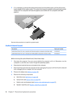
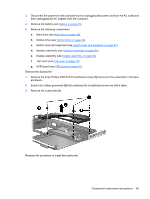
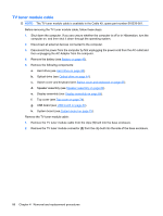
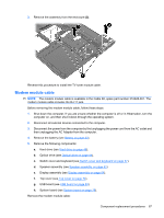
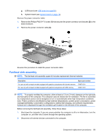
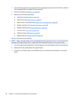
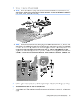
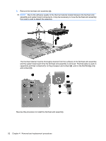
3. Remove the assembly from the enclosure (3). Reverse this procedure to install the TV tuner module cable. Modem module cable NOTE: The modem module cable is available in the Cable Kit, spare part number 516328-001. The modem module cable includes the RJ-11 jack. Before removing the modem module cable, follow these steps: 1. Shut down the computer. If you are unsure whether the computer is off or in Hibernation, turn the computer on, and then shut it down through the operating system. 2. Disconnect all external devices connected to the computer. 3. Disconnect the power from the computer by first unplugging the power cord from the AC outlet and then unplugging the AC Adapter from the computer. 4. Remove the battery (see Battery on page 43). 5. Remove the following components: a. Hard drive (see Hard drive on page 48). b. Optical drive (see Optical drive on page 44). c. Switch cover and keyboard (see Switch cover and keyboard on page 57). d. Speaker assembly (see Speaker assembly on page 62). e. Display assembly (see Display assembly on page 64). f. Top cover (see Top cover on page 74). g. USB board (see USB board on page 83). h. System board (see System board on page 79). Remove the modem module cable: Component replacement procedures 87
-
 1
1 -
2
-
3
-
4
-
5
-
6
-
7
-
8
-
9
-
10
-
11
-
12
-
13
-
14
-
15
-
16
-
17
-
18
-
19
-
20
-
21
-
22
-
23
-
24
-
25
-
26
-
27
-
28
-
29
-
30
-
31
-
32
-
33
-
34
-
35
-
36
-
37
-
38
-
39
-
40
-
41
-
42
-
43
-
44
-
45
-
46
-
47
-
48
-
49
-
50
-
51
-
52
-
53
-
54
-
55
-
56
-
57
-
58
-
59
-
60
-
61
-
62
-
63
-
64
-
65
-
66
-
67
-
68
-
69
-
70
-
71
-
72
-
73
-
74
-
75
-
76
-
77
-
78
-
79
-
80
-
81
-
82
-
83
-
84
-
85
-
86
-
87
-
88
-
89
-
 90
90 -
 91
91 -
 92
92 -
 93
93 -
 94
94 -
 95
95 -
 96
96 -
 97
97 -
 98
98 -
 99
99 -
 100
100 -
101
-
102
-
103
-
104
-
105
-
106
-
107
-
108
-
109
-
110
-
111
-
112
-
113
-
114
-
115
-
116
-
117
-
118
-
119
-
120
-
121
-
122
-
123
-
124
-
125
-
126
-
127
-
128
-
129
-
130
-
131
-
132
-
133
-
134
-
135
-
136
-
137
-
138
-
139
-
140
-
141
-
142
-
143
-
144
-
145
-
146
-
147
-
148
-
149
-
150
-
151
-
152
-
153
-
154
-
155
-
156
-
157
-
158
-
159
-
160
-
161
-
162
-
163
-
164
 |
 |
