HP Dv7-2170us HP Pavilion dv7 Entertainment PC - Maintenance and Service Guide - Page 78
Two Phillips PM2.5×6.5 screws, Remove the display bezel
 |
UPC - 884962256558
View all HP Dv7-2170us manuals
Add to My Manuals
Save this manual to your list of manuals |
Page 78 highlights
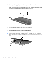
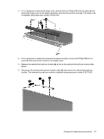
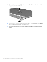
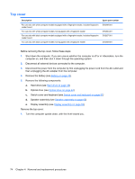
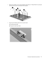
19. If it is necessary to replace the display bezel or any of the display assembly internal components, remove the following screw covers and screws: (1) Two rubber screw covers on the display bezel bottom edge. The display rubber screw covers are included in the Display Rubber Kit, spare part number 516308-001. (2) Two Phillips PM2.5×6.5 screws 20. Flex the inside edges of the top edge (1), the left and right sides (2), and the bottom edge of the display bezel (3) until the bezel disengages from the display enclosure. 21. Remove the display bezel (4). The display bezel is available using the spare part number 516305-001. 22. If it is necessary to replace webcam/microphone module, release the module from the display bezel (1) as far as the webcam/microphone module cable allows. 70 Chapter 4 Removal and replacement procedures
-
 1
1 -
2
-
3
-
4
-
5
-
6
-
7
-
8
-
9
-
10
-
11
-
12
-
13
-
14
-
15
-
16
-
17
-
18
-
19
-
20
-
21
-
22
-
23
-
24
-
25
-
26
-
27
-
28
-
29
-
30
-
31
-
32
-
33
-
34
-
35
-
36
-
37
-
38
-
39
-
40
-
41
-
42
-
43
-
44
-
45
-
46
-
47
-
48
-
49
-
50
-
51
-
52
-
53
-
54
-
55
-
56
-
57
-
58
-
59
-
60
-
61
-
62
-
63
-
64
-
65
-
66
-
67
-
68
-
69
-
70
-
71
-
72
-
 73
73 -
 74
74 -
 75
75 -
 76
76 -
 77
77 -
 78
78 -
 79
79 -
 80
80 -
 81
81 -
 82
82 -
 83
83 -
84
-
85
-
86
-
87
-
88
-
89
-
90
-
91
-
92
-
93
-
94
-
95
-
96
-
97
-
98
-
99
-
100
-
101
-
102
-
103
-
104
-
105
-
106
-
107
-
108
-
109
-
110
-
111
-
112
-
113
-
114
-
115
-
116
-
117
-
118
-
119
-
120
-
121
-
122
-
123
-
124
-
125
-
126
-
127
-
128
-
129
-
130
-
131
-
132
-
133
-
134
-
135
-
136
-
137
-
138
-
139
-
140
-
141
-
142
-
143
-
144
-
145
-
146
-
147
-
148
-
149
-
150
-
151
-
152
-
153
-
154
-
155
-
156
-
157
-
158
-
159
-
160
-
161
-
162
-
163
-
164
 |
 |
