HP Dv7-2170us HP Pavilion dv7 Entertainment PC - Maintenance and Service Guide - Page 91
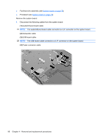
USB board, Remove the Phillips PM2.5×5.0 screw
 |
UPC - 884962256558
View all HP Dv7-2170us manuals
Add to My Manuals
Save this manual to your list of manuals |
Page 91 highlights
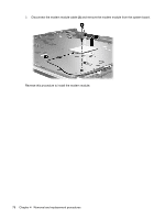
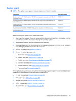
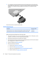
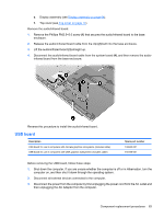
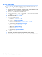
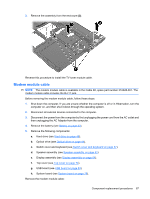
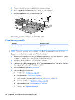
e. Display assembly (see Display assembly on page 64). f. Top cover (see Top cover on page 74). Remove the audio/infrared board: 1. Remove the Phillips PM2.5×5.0 screw (1) that secures the audio/infrared board to the base enclosure. 2. Release the audio/infrared board cable from the clip (2) built into the base enclosure. 3. Lift the audio/infrared board (3) straight up. 4. Disconnect the audio/infrared board cable from the system board (4), and then remove the audioinfrared board from the base enclosure. Reverse this procedure to install the audio/infrared board. USB board Description USB board for use in computers with discrete graphics subsystems (includes cable) USB board for use in computers with UMA graphics subsystems (includes cable) Spare part number 516332-001 518168-001 Before removing the USB board, follow these steps: 1. Shut down the computer. If you are unsure whether the computer is off or in Hibernation, turn the computer on, and then shut it down through the operating system. 2. Disconnect all external devices connected to the computer. 3. Disconnect the power from the computer by first unplugging the power cord from the AC outlet and then unplugging the AC Adapter from the computer. Component replacement procedures 83
-
 1
1 -
2
-
3
-
4
-
5
-
6
-
7
-
8
-
9
-
10
-
11
-
12
-
13
-
14
-
15
-
16
-
17
-
18
-
19
-
20
-
21
-
22
-
23
-
24
-
25
-
26
-
27
-
28
-
29
-
30
-
31
-
32
-
33
-
34
-
35
-
36
-
37
-
38
-
39
-
40
-
41
-
42
-
43
-
44
-
45
-
46
-
47
-
48
-
49
-
50
-
51
-
52
-
53
-
54
-
55
-
56
-
57
-
58
-
59
-
60
-
61
-
62
-
63
-
64
-
65
-
66
-
67
-
68
-
69
-
70
-
71
-
72
-
73
-
74
-
75
-
76
-
77
-
78
-
79
-
80
-
81
-
82
-
83
-
84
-
85
-
 86
86 -
 87
87 -
 88
88 -
 89
89 -
 90
90 -
 91
91 -
 92
92 -
 93
93 -
 94
94 -
 95
95 -
 96
96 -
97
-
98
-
99
-
100
-
101
-
102
-
103
-
104
-
105
-
106
-
107
-
108
-
109
-
110
-
111
-
112
-
113
-
114
-
115
-
116
-
117
-
118
-
119
-
120
-
121
-
122
-
123
-
124
-
125
-
126
-
127
-
128
-
129
-
130
-
131
-
132
-
133
-
134
-
135
-
136
-
137
-
138
-
139
-
140
-
141
-
142
-
143
-
144
-
145
-
146
-
147
-
148
-
149
-
150
-
151
-
152
-
153
-
154
-
155
-
156
-
157
-
158
-
159
-
160
-
161
-
162
-
163
-
164
 |
 |
