HP Dv7-2170us HP Pavilion dv7 Entertainment PC - Maintenance and Service Guide - Page 73
CAUTION, Steps 5 through 18 provide display assembly internal component removal information
 |
UPC - 884962256558
View all HP Dv7-2170us manuals
Add to My Manuals
Save this manual to your list of manuals |
Page 73 highlights
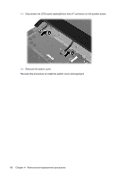
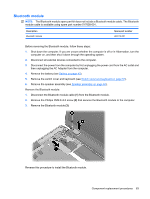
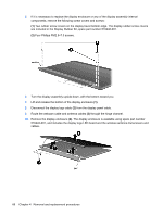
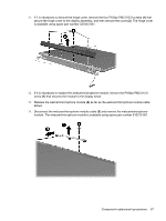
2. Remove the WLAN antenna cables from the clips (3) built into the top cover. CAUTION: Support the display assembly when removing the following screws. Failure to support the display assembly can result in damage to the display assembly and other computer components. 3. Remove the four Phillips PM2.5×7.0 screws (1) that secure the display assembly to the computer. 4. Remove the display assembly (2). NOTE: Steps 5 through 18 provide display assembly internal component removal information for computer models equipped with flush glass display assemblies. See steps 19 through 28 for display assembly internal component removal information for computer models equipped with BrightView display assemblies. Component replacement procedures 65
-
 1
1 -
2
-
3
-
4
-
5
-
6
-
7
-
8
-
9
-
10
-
11
-
12
-
13
-
14
-
15
-
16
-
17
-
18
-
19
-
20
-
21
-
22
-
23
-
24
-
25
-
26
-
27
-
28
-
29
-
30
-
31
-
32
-
33
-
34
-
35
-
36
-
37
-
38
-
39
-
40
-
41
-
42
-
43
-
44
-
45
-
46
-
47
-
48
-
49
-
50
-
51
-
52
-
53
-
54
-
55
-
56
-
57
-
58
-
59
-
60
-
61
-
62
-
63
-
64
-
65
-
66
-
67
-
 68
68 -
 69
69 -
 70
70 -
 71
71 -
 72
72 -
 73
73 -
 74
74 -
 75
75 -
 76
76 -
 77
77 -
 78
78 -
79
-
80
-
81
-
82
-
83
-
84
-
85
-
86
-
87
-
88
-
89
-
90
-
91
-
92
-
93
-
94
-
95
-
96
-
97
-
98
-
99
-
100
-
101
-
102
-
103
-
104
-
105
-
106
-
107
-
108
-
109
-
110
-
111
-
112
-
113
-
114
-
115
-
116
-
117
-
118
-
119
-
120
-
121
-
122
-
123
-
124
-
125
-
126
-
127
-
128
-
129
-
130
-
131
-
132
-
133
-
134
-
135
-
136
-
137
-
138
-
139
-
140
-
141
-
142
-
143
-
144
-
145
-
146
-
147
-
148
-
149
-
150
-
151
-
152
-
153
-
154
-
155
-
156
-
157
-
158
-
159
-
160
-
161
-
162
-
163
-
164
 |
 |

2.
Remove the WLAN antenna cables from the clips
(3)
built into the top cover.
CAUTION:
Support the display assembly when removing the following screws. Failure to support
the display assembly can result in damage to the display assembly and other computer
components.
3.
Remove the four Phillips PM2.5×7.0 screws
(1)
that secure the display assembly to the computer.
4.
Remove the display assembly
(2)
.
NOTE:
Steps 5 through 18 provide display assembly internal component removal information for
computer models equipped with flush glass display assemblies. See steps 19 through 28 for display
assembly internal component removal information for computer models equipped with BrightView
display assemblies.
Component replacement procedures
65