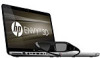
HP ENVY 17-1100 HP ENVY 17 - Maintenance and Service Guide
HP ENVY 17-1100 - 3D Edition Notebook PC Manual
 |
View all HP ENVY 17-1100 manuals
Add to My Manuals
Save this manual to your list of manuals |
HP ENVY 17-1100 manual content summary:
- HP ENVY 17-1100 | HP ENVY 17 - Maintenance and Service Guide - Page 1
HP ENVY 17 Maintenance and Service Guide - HP ENVY 17-1100 | HP ENVY 17 - Maintenance and Service Guide - Page 2
is a trademark of Intel Corporation in the U.S. and other countries. Microsoft, Windows, and Windows Vista are U.S. registered trademarks of Microsoft Corporation. The information contained herein is subject to change without notice. The only warranties for HP products and services are set forth in - HP ENVY 17-1100 | HP ENVY 17 - Maintenance and Service Guide - Page 3
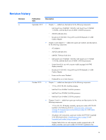
640-GB, 7200-rpm hard drive ◦ Intel Quad Core i7-840QM 1.86-GHz, Intel Quad Core i7-740QM 1.73-GHz, and Intel Dual Core i5-450M 2.40-GHz : ◦ 17.3-in, WVA 3D, LED, AntiGlare display ◦ Intel Dual Core i5-580M 2.66-GHz processor ◦ Intel Dual Core i5-560M 2.66-GHz processor ◦ Intel Dual Core iii - HP ENVY 17-1100 | HP ENVY 17 - Maintenance and Service Guide - Page 4
board, spare part number 631398-001 (updated in the following locations: Miscellaneous parts on page 26 and Sequential part number listing on page 27) ◦ Intel Dual Core i5-580M 2.66-GHz processor, spare part number 625825-001 (updated in the following locations: Computer major components on page 18 - HP ENVY 17-1100 | HP ENVY 17 - Maintenance and Service Guide - Page 5
Safety warning notice WARNING! To reduce the possibility of heat-related injuries or of overheating the device, do not place the device directly on your lap or obstruct the device air vents. Use the device only on a hard, flat surface. Do not allow another hard surface, such as an adjoining optional - HP ENVY 17-1100 | HP ENVY 17 - Maintenance and Service Guide - Page 6
vi Safety warning notice - HP ENVY 17-1100 | HP ENVY 17 - Maintenance and Service Guide - Page 7
Front components ...11 Left-side components ...12 Right-side components ...14 Bottom components ...15 3 Illustrated parts catalog 16 Service tag ...17 Computer major components 18 Display assembly subcomponents 23 Plastics Kit ...24 Mass storage devices ...25 Miscellaneous parts ...26 Sequential - HP ENVY 17-1100 | HP ENVY 17 - Maintenance and Service Guide - Page 8
Component replacement procedures 36 Service tag ...36 Computer feet ...37 Battery ...38 Primary hard drive 39 RTC battery ...42 Memory module ... 6 Specifications ...83 Computer specifications ...83 17.3-inch, WVA, FHD, LED AntiGlare display specifications 84 17.3-inch, SVA, HD+, LED AntiGlare - HP ENVY 17-1100 | HP ENVY 17 - Maintenance and Service Guide - Page 9
) ...97 Universal Serial Bus ...97 9 Power cord set requirements 98 Requirements for all countries 98 Requirements for specific countries and regions 99 10 Recycling ...100 Battery ...100 Display ...100 Index ...106 ix - HP ENVY 17-1100 | HP ENVY 17 - Maintenance and Service Guide - Page 10
x - HP ENVY 17-1100 | HP ENVY 17 - Maintenance and Service Guide - Page 11
Name Processors Chipset Graphics Description HP ENVY 17 Intel® Quad Core™ processors (support Intel Turbo Boost Technology): ● Intel Quad Core i7-840QM 1.86-GHz processor (SC turbo up to 3.20-MHz), 8-MB L3 cache, 1333-MHz front side bus (FSB), 45-W ● Intel Quad Core i7-820QM 1.73-GHz processor (SC - HP ENVY 17-1100 | HP ENVY 17 - Maintenance and Service Guide - Page 12
) display; typical brightness: 300 nits 17.3-in, SVA high-definition+ (HD+), cables Supports flush display panel cover Supports Supports dual-channel memory Supports up to 8192 GB of system RAM 1) ● 4096-MB total system memory (2048 × 2) Supports 6.35-cm (2.5-in) hard drives in 12.5-mm (.49- - HP ENVY 17-1100 | HP ENVY 17 - Maintenance and Service Guide - Page 13
500-GB hard drive (7200-rpm, 9.5-mm) ● 640 GB: 320-GB hard drive (7200-rpm, 9.5-mm) × 2 Supports the following single hard drive configurations: ● 1 TB: 1-TB hard drive (5200-rpm, 12.5-mm) ● 750 GB: 750 Beats audio Supports Microsoft Premium Requirements Integrated HP triple bass reflex subwoofer 3 - HP ENVY 17-1100 | HP ENVY 17 - Maintenance and Service Guide - Page 14
Description HP ENVY HD webcam (fixed, no tilt) with activity LED, 1280×800 by 24 frames per second Integrated 10/100/1000 GB network interface card (NIC) Integrated wireless local area network (WLAN) options by way of wireless module: Two WLAN antennas built into display assembly Support for - HP ENVY 17-1100 | HP ENVY 17 - Maintenance and Service Guide - Page 15
Security Operating system Serviceability Description Taps enable by default 120-W HP Smart Adapter and 65-W Slim Travel Adapter AC adapters with localized cable plug support (3-wire plug with ground pin, supports 3-pin DC connector) Support for the following batteries: ● 9-cell, 2.80-Ah - HP ENVY 17-1100 | HP ENVY 17 - Maintenance and Service Guide - Page 16
2 External component identification Top components Display components Item (1) (2) (3) (4) Component WLAN antennas (2)* Internal microphones (2) Webcam light Webcam Description Send and receive wireless signals to communicate with wireless local area networks. Record sound. On: The webcam is in - HP ENVY 17-1100 | HP ENVY 17 - Maintenance and Service Guide - Page 17
Environmental Notices that applies to your country or region. These notices are located in Help and Support. Button Component Power button* Description ● When the computer is off, press the button to System and Security > Power Options, or refer to the HP Notebook Reference Guide. Top components 7 - HP ENVY 17-1100 | HP ENVY 17 - Maintenance and Service Guide - Page 18
Keys Item (1) (2) (3) (4) (5) (6) (7) Component esc key fn key Windows logo key Action keys Windows applications key Integrated numeric keypad Optical drive eject key Description Displays system information when pressed in combination with the fn key. Executes frequently used system functions - HP ENVY 17-1100 | HP ENVY 17 - Maintenance and Service Guide - Page 19
Lights Item (1) Component TouchPad off indicator (2) Caps lock light (3) Power light (4) Mute light (5) Wireless light Description ● Amber: The TouchPad is off. ● Off: The TouchPad is on. ● White: Caps lock is on. ● Off: Caps lock is off. ● White: The computer is on. ● Blinking white: The - HP ENVY 17-1100 | HP ENVY 17 - Maintenance and Service Guide - Page 20
TouchPad Item (1) Component TouchPad off indicator (2) Left TouchPad button (3) Right TouchPad button (4) TouchPad zone Description Turns the TouchPad on and off. Quickly double-tap the TouchPad off indicator to turn the TouchPad on and off. Functions like the left button on an external - HP ENVY 17-1100 | HP ENVY 17 - Maintenance and Service Guide - Page 21
or in Hibernation. ● Blinking white: The hard drive is being accessed. ● Amber: HP ProtectSmart Hard Drive Protection has temporarily parked the hard drive. NOTE: For information on HP ProtectSmart Hard Drive Protection, refer to the HP Notebook Reference Guide. Produce sound. Front components 11 - HP ENVY 17-1100 | HP ENVY 17 - Maintenance and Service Guide - Page 22
such as a high performance monitor or projector. Connects an optional video or audio device, such as a high-definition television, or any compatible digital or audio component. Connects a high-performance eSATA component, such as an eSATA external hard drive, or connects an optional USB device - HP ENVY 17-1100 | HP ENVY 17 - Maintenance and Service Guide - Page 23
Item (8) (9) Component Audio-out (headphone) jack/Audio-in (microphone) jack Audio-out (headphone) jack Description Produces sound when connected to optional powered stereo speakers, headphones, earbuds, a headset, or television audio. Also connects an optional headset microphone. WARNING! To - HP ENVY 17-1100 | HP ENVY 17 - Maintenance and Service Guide - Page 24
. This can cause damage to the computer. ● Off: The computer is running on battery power. ● Blinking amber: The battery has reached a low battery level, a critical battery level, or there is a battery error. ● Amber: A battery is charging. ● White: The computer is connected to external power and the - HP ENVY 17-1100 | HP ENVY 17 - Maintenance and Service Guide - Page 25
bay (3) Vents (7) (4) Hard drive bay (5) Memory module compartment (6) Battery release latch Description Contains the subwoofer speaker. Holds the battery. NOTE: The battery is preinstalled in the battery bay at the factory. Enable airflow to cool internal components. NOTE: The computer - HP ENVY 17-1100 | HP ENVY 17 - Maintenance and Service Guide - Page 26
3 Illustrated parts catalog 16 Chapter 3 Illustrated parts catalog - HP ENVY 17-1100 | HP ENVY 17 - Maintenance and Service Guide - Page 27
provide the computer serial number and model number provided on the service tag. Item (1) (2) (3) Component Product name Serial number (s/n) a service technician determine what components and parts are needed. This is the alphanumeric identifier used to locate documents, drivers, and support for - HP ENVY 17-1100 | HP ENVY 17 - Maintenance and Service Guide - Page 28
Computer major components 18 Chapter 3 Illustrated parts catalog - HP ENVY 17-1100 | HP ENVY 17 - Maintenance and Service Guide - Page 29
Display assembly (includes display panel cable, webcam/microphone module and cable, and 2 wireless antenna cables and transceivers): 17.3-in AG, FG, 3D 620775-001 17.3-in AG, FG, FHD 603774-001 17.3-in AG, FG, HD+ 603773-001 NOTE: See Display assembly subcomponents on page 23 for more display - HP ENVY 17-1100 | HP ENVY 17 - Maintenance and Service Guide - Page 30
Intel Core i7-820QM 1.73-GHz (SC turbo up to 3.06-GHz), 45W processor 583053-001 Intel Core i7-740QM 1.73-GHz (SC turbo up to 2.93-GHz), 45W processor 612259-001 Intel Core i7-720QM -001 Battery: 9-cell, 93-Wh, 2.8-Ah, Li-ion battery 593550-001 6-cell, 62-Wh, 2.8-Ah, Li-ion battery 593562- - HP ENVY 17-1100 | HP ENVY 17 - Maintenance and Service Guide - Page 31
Item (16) (17) (18) (19) Description Spare part number Hard drive (2, includes hard drive includes primary hard drive bracket and cable and secondary hard drive bracket and cable) 603772-001 RTC battery 602745-001 Memory modules (2, PC3, 10600, 1333-MHz) 4-GB 599092-001 2-GB 598856-001 - HP ENVY 17-1100 | HP ENVY 17 - Maintenance and Service Guide - Page 32
, the United Kingdom, Uruguay, Uzbekistan, Vanuatu, Venezuela, Vietnam, Yemen, Zaire, Zambia, and Zimbabwe 582564-002 Intel Centrino Advanced-N 6200 802.11a/b/g/n WLAN module 572509-001 Intel Centrino Advanced-N 6200 802.11a/b/g WLAN module 572510-001 22 Chapter 3 Illustrated parts catalog - HP ENVY 17-1100 | HP ENVY 17 - Maintenance and Service Guide - Page 33
Display assembly subcomponents Item (1) (2) (3) (4) (5) (6) (7) Description Spare part number Webcam/microphone module 603779-001 Bluetooth module 537921-001 Display Cable Kit (include display panel cable, Bluetooth module cable, and webcam/microphone module cable): For use with computer - HP ENVY 17-1100 | HP ENVY 17 - Maintenance and Service Guide - Page 34
Plastics Kit Item (1) (2) Description Plastics Kit, includes: memory module compartment cover (includes 2 captive screws, secured by C-clips) Hard drive cover (includes 2 captive screws, secured by C-clips) Spare part number 603795-001 24 Chapter 3 Illustrated parts catalog - HP ENVY 17-1100 | HP ENVY 17 - Maintenance and Service Guide - Page 35
Mass storage devices Item (1) (2) (3) Description Optical drive: Blu-ray ROM DVD±RW Super Multi Double-Layer Drive DVD±RW and CD-RW Super Multi Double-Layer Combo Drive Hard drive (includes hard drive brackets and hard drive cables): Primary hard drive Secondary hard drive 640-GB, 7200-rpm 500-GB, - HP ENVY 17-1100 | HP ENVY 17 - Maintenance and Service Guide - Page 36
Miscellaneous parts Description AC adapter: 135-W HP Smart AC adapter (PFC RC/V 3-wire) 120-W HP Smart AC adapter (PFC RC/V 3-wire) 3D glasses with nose pieces Protective case for 3D glasses Power cord: For use in Australia For use in - HP ENVY 17-1100 | HP ENVY 17 - Maintenance and Service Guide - Page 37
the People's Republic of China Power cord for use in South Korea Power cord for use in India Bluetooth module Intel Centrino Advanced-N 6200 802.11a/b/g/n WLAN module Intel Centrino Advanced-N 6200 802.11a/b/g WLAN module Broadcom 43224 802.11a/b/g/n 2x2 WiFi Adapter for use in Antigua and Barbuda - HP ENVY 17-1100 | HP ENVY 17 - Maintenance and Service Guide - Page 38
Intel Core i7-720QM 1.60-GHz (SC turbo up to 2.80-GHz), 45W processor (includes replacement thermal material) 9-cell, 93-Wh, 2.8-Ah, Li-ion battery 6-cell, 62-Wh, 2.8-Ah, Li-ion battery Intel cable, and 2 wireless antenna cables and transceivers) 17.3-in AG, FG, FHD display assembly (includes display - HP ENVY 17-1100 | HP ENVY 17 - Maintenance and Service Guide - Page 39
for more Plastics Kit component information. Speakers (include cable) Screw Kit Rubber Feet Kit (includes 5 rubber feet) Fan/heat sink assembly for use only with Intel Core i5, 35-W processors (includes replacement thermal material) Sequential part number listing 29 - HP ENVY 17-1100 | HP ENVY 17 - Maintenance and Service Guide - Page 40
use only with Intel Core i7, 45-W processors (includes replacement thermal material) 120-W HP Smart AC adapter (PFC RC/V 3-wire) Intel Core i7-740QM 1.73-GHz 1 GB of discrete graphics subsystem memory and replacement thermal material) 17.3-in AG, FG, 3D display assembly (includes display panel cable - HP ENVY 17-1100 | HP ENVY 17 - Maintenance and Service Guide - Page 41
plastic parts. Use care when handling the plastic parts. Apply pressure only at the points designated in the maintenance instructions. Cables and connectors CAUTION: When servicing the computer, be sure that cables are placed in their proper locations during the reassembly process. Improper cable - HP ENVY 17-1100 | HP ENVY 17 - Maintenance and Service Guide - Page 42
Drive handling CAUTION: Drives are fragile components that must be handled with care. To prevent damage to the computer, damage to a drive, or loss of information, observe these precautions: Before removing or inserting a hard drive, shut down the computer. If you are unsure whether the computer is - HP ENVY 17-1100 | HP ENVY 17 - Maintenance and Service Guide - Page 43
CAUTION: To prevent damage to the computer when you are removing or installing internal components, observe these precautions: Keep components in their electrostatic-safe containers until you are ready to install them. Before touching an electronic component, discharge static electricity by using - HP ENVY 17-1100 | HP ENVY 17 - Maintenance and Service Guide - Page 44
. ● Use a wrist strap connected to a properly grounded work surface and use properly grounded tools and equipment. ● Use conductive field service tools, such as cutters, screwdrivers, and vacuums. ● When fixtures must directly contact dissipative surfaces, use fixtures made only of staticsafe - HP ENVY 17-1100 | HP ENVY 17 - Maintenance and Service Guide - Page 45
(heel, toe, or boot straps) can be used at standing workstations and are compatible with most types of shoes or boots. On conductive floors or dissipative floor mats, or floor mats with hard ties to the ground ● Field service kits ● Static awareness labels ● Material-handling packages ● - HP ENVY 17-1100 | HP ENVY 17 - Maintenance and Service Guide - Page 46
tag When ordering parts or requesting information, provide the computer serial number and model number provided on the service tag. Item (1) (2) (3) Component Product name Serial number (s/n) Part number/Product number (p/n) 36 Chapter 4 Removal and replacement procedures Description This - HP ENVY 17-1100 | HP ENVY 17 - Maintenance and Service Guide - Page 47
Item (4) (5) Component Model description Warranty period Description This is the alphanumeric identifier used to locate documents, drivers, and support for the computer. This number describes the duration of the warranty period for the computer. Computer feet The computer feet are adhesive-backed - HP ENVY 17-1100 | HP ENVY 17 - Maintenance and Service Guide - Page 48
, with the front toward you. 2. Slide the battery release latch (1) to release the battery. 3. Pivot the front edge of the battery (2) upward. 4. Remove the battery from the computer. To insert the battery, insert the rear edge of the battery into the battery bay, and pivot the front edge of the - HP ENVY 17-1100 | HP ENVY 17 - Maintenance and Service Guide - Page 49
from the computer by first unplugging the power cord from the AC outlet and then unplugging the AC adapter from the computer. 4. Remove the battery (see Battery on page 38). 5. Remove the memory module compartment cover (see Memory module on page 43). 6. Remove the hard drive cover (see Primary hard - HP ENVY 17-1100 | HP ENVY 17 - Maintenance and Service Guide - Page 50
Remove the primary hard drive: 1. Loosen the two captive Phillips screws that secure the hard drive cover to the computer. 2. Pivot the front edge of the hard drive cover upward. 3. Remove the hard drive cover. The hard drive cover is included in the Plastics Kit, spare part number 603795-001. 4. - HP ENVY 17-1100 | HP ENVY 17 - Maintenance and Service Guide - Page 51
5. Use the Mylar tabs to remove the primary hard drive from the computer. 6. If it is necessary to replace the primary hard drive bracket, remove the four Phillips PM3.0×3.0 screws (1) that secure the bracket to the primary hard drive. 7. Lift the primary hard drive bracket straight up (2) and - HP ENVY 17-1100 | HP ENVY 17 - Maintenance and Service Guide - Page 52
power from the computer by first unplugging the power cord from the AC outlet and then unplugging the AC adapter from the computer. 4. Remove the battery (see Battery on page 38). 5. Remove the hard drive cover (see Primary hard drive on page 39). Remove the RTC - HP ENVY 17-1100 | HP ENVY 17 - Maintenance and Service Guide - Page 53
power from the computer by first unplugging the power cord from the AC outlet and then unplugging the AC adapter from the computer. 4. Remove the battery (see Battery on page 38). 5. Remove the hard drive cover (see Primary hard drive on page 39). Remove the memory module: 1. Loosen the two captive - HP ENVY 17-1100 | HP ENVY 17 - Maintenance and Service Guide - Page 54
5. Remove the memory module (2) by pulling it away from the slot at an angle. NOTE: Memory modules are designed with a notch (3) to prevent incorrect insertion into the memory module slot. Reverse this procedure to install a memory module. 44 Chapter 4 Removal and replacement procedures - HP ENVY 17-1100 | HP ENVY 17 - Maintenance and Service Guide - Page 55
from the computer by first unplugging the power cord from the AC outlet and then unplugging the AC adapter from the computer. 4. Remove the battery (see Battery on page 38). 5. Remove the hard drive cover (see Primary hard drive on page 39). 6. Remove the memory module compartment cover (see Memory - HP ENVY 17-1100 | HP ENVY 17 - Maintenance and Service Guide - Page 56
Remove the secondary hard drive: 1. Disconnect the secondary hard drive cable from the system board, and then release the cable from the clips and routing channel built into the base enclosure. 2. Remove the four Phillips PM2.5×6.0 screws that secure the secondary hard drive to the computer. 3. Use - HP ENVY 17-1100 | HP ENVY 17 - Maintenance and Service Guide - Page 57
4. Remove the secondary hard drive (2) by sliding it up and away from the computer at an angle. 5. If it is necessary to replace the secondary hard drive bracket, remove the four Phillips PM3.0×3.0 screws (1) that secure the bracket to the secondary hard drive. 6. Lift the secondary hard drive - HP ENVY 17-1100 | HP ENVY 17 - Maintenance and Service Guide - Page 58
7. If it is necessary to replace the secondary hard drive connector cable, disconnect the cable from the hard drive. The secondary hard drive bracket and secondary hard drive connector cable are included in the Hard Drive Hardware Kit, spare part number 603772-001. Reverse this procedure to - HP ENVY 17-1100 | HP ENVY 17 - Maintenance and Service Guide - Page 59
002 Intel Centrino Advanced-N 6200 802.11a/b/g/n WLAN module 572509-001 Intel Centrino module to restore device functionality, and then contact technical support. Before removing the WLAN module, follow these steps from the computer. 4. Remove the battery (see Battery on page 38). 5. Remove the memory - HP ENVY 17-1100 | HP ENVY 17 - Maintenance and Service Guide - Page 60
Remove the WLAN module: 1. Disconnect the WLAN antenna cables (1) from the terminals on the WLAN module. NOTE: The 1/black WLAN antenna cable is connected to the WLAN module 1/Main terminal. The 2/gray WLAN antenna cable is connected to the WLAN module 2/Aux terminal. 2. Remove the two Phillips PM2 - HP ENVY 17-1100 | HP ENVY 17 - Maintenance and Service Guide - Page 61
power from the computer by first unplugging the power cord from the AC outlet and then unplugging the AC adapter from the computer. 4. Remove the battery (see Battery on page 38). 5. Remove the memory module compartment cover (see Memory module on page 43). Component replacement procedures 51 - HP ENVY 17-1100 | HP ENVY 17 - Maintenance and Service Guide - Page 62
Remove the keyboard: 1. Remove the three Phillips PM 2.5×5.0 screws (1) and the Phillips PM 2.5×7.0 (2) screw that secure the keyboard to the computer. 2. Lift the rear edge of the keyboard (1) until it rests at an angle. 3. Slide the keyboard (2) toward the display until the tabs on the front edge - HP ENVY 17-1100 | HP ENVY 17 - Maintenance and Service Guide - Page 63
from the computer by first unplugging the power cord from the AC outlet and then unplugging the AC adapter from the computer. 4. Remove the battery (see Battery on page 38). 5. Remove the memory module compartment cover (see Memory module on page 43). 6. Remove the keyboard (see Keyboard on page 51 - HP ENVY 17-1100 | HP ENVY 17 - Maintenance and Service Guide - Page 64
screws (2) that secure the top cover to the computer. 4. Remove the three Phillips PM2.5×5.0 screws (3) that secure the top cover to the computer in the battery bay. 5. Turn the computer display-side up, with the front toward you. 6. Open the computer as far as it will open. 7. Release the ZIF - HP ENVY 17-1100 | HP ENVY 17 - Maintenance and Service Guide - Page 65
11. Remove the top cover (2). Reverse this procedure to install the top cover. Component replacement procedures 55 - HP ENVY 17-1100 | HP ENVY 17 - Maintenance and Service Guide - Page 66
computer by first unplugging the power cord from the AC outlet and then unplugging the AC adapter from the computer. 4. Remove the battery (see Battery on page 38), and then remove the following components: a. memory module compartment cover (see Memory module on page 43) b. Keyboard (see Keyboard - HP ENVY 17-1100 | HP ENVY 17 - Maintenance and Service Guide - Page 67
computer by first unplugging the power cord from the AC outlet and then unplugging the AC adapter from the computer. 4. Remove the battery (see Battery on page 38), and then remove the following components: a. memory module compartment cover (see Memory module on page 43) b. Keyboard (see Keyboard - HP ENVY 17-1100 | HP ENVY 17 - Maintenance and Service Guide - Page 68
computer by first unplugging the power cord from the AC outlet and then unplugging the AC adapter from the computer. 4. Remove the battery (see Battery on page 38), and then remove the following components: a. memory module compartment cover (see Memory module on page 43) b. Keyboard (see Keyboard - HP ENVY 17-1100 | HP ENVY 17 - Maintenance and Service Guide - Page 69
Remove the optical drive: 1. Remove the three Phillips PM2.5×5.0 screws (1) that secure the optical drive to the computer. 2. Slide the optical drive (2) to the right to disconnect it from the system board. 3. Remove the optical drive (3) by lifting it straight up. Reverse this procedure to install - HP ENVY 17-1100 | HP ENVY 17 - Maintenance and Service Guide - Page 70
computer by first unplugging the power cord from the AC outlet and then unplugging the AC adapter from the computer. 4. Remove the battery (see Battery on page 38), and then remove the following components: a. memory module compartment cover (see Memory module on page 43) b. Keyboard (see Keyboard - HP ENVY 17-1100 | HP ENVY 17 - Maintenance and Service Guide - Page 71
from the computer by first unplugging the power cord from the AC outlet and then unplugging the AC adapter from the computer. 4. Remove the battery (see Battery on page 38), and then remove the following components: a. Hard drives (see Primary hard drive on page 39 and see Secondary hard drive on - HP ENVY 17-1100 | HP ENVY 17 - Maintenance and Service Guide - Page 72
Remove the system board: 1. Disconnect the following cables from the system board: (1) Bluetooth module cable (2) Display panel cable (3) USB/Card Reader board cable (4) Speaker cable 62 Chapter 4 Removal and replacement procedures - HP ENVY 17-1100 | HP ENVY 17 - Maintenance and Service Guide - Page 73
2. Disconnect the subwoofer cable (1) and the power connector cable (2) from the system board. 3. Remove the two Phillips PM2.5×5.0 screws that secure the system board to the base enclosure. 4. Use the optical drive connector (1) to lift the right side of the system board (2) until it rests at an - HP ENVY 17-1100 | HP ENVY 17 - Maintenance and Service Guide - Page 74
5. Remove the system board (3) by sliding it up and to the right at an angle. Reverse this procedure to install the system board. 64 Chapter 4 Removal and replacement procedures - HP ENVY 17-1100 | HP ENVY 17 - Maintenance and Service Guide - Page 75
thermal material. Description For use only with Intel Core i7, 45-W processors For use only with Intel Core i5, 35-W processors Spare part and then unplugging the AC adapter from the computer. 4. Remove the battery (see Battery on page 38), and then remove the following components: a. Hard drives - HP ENVY 17-1100 | HP ENVY 17 - Maintenance and Service Guide - Page 76
is removed: ● Thermal paste is used on the processor (1) and the heat sink section (2) that services it ● Thermal pads are used on the graphics subsystem chip (3) and the heat sink section (4) that services it ● Thermal pads are used on the system board capacitors (5) and the heat sink section - HP ENVY 17-1100 | HP ENVY 17 - Maintenance and Service Guide - Page 77
Intel Core i7-820QM 1.73-GHz (SC turbo up to 3.06-GHz), 45-W processor Intel Core i7-740QM 1.73-GHz (SC turbo up to 2.93-GHz), 45-W processor Intel Core i7-720QM 1.60-GHz (SC turbo up to 2.80-GHz), 45-W processor Intel from the computer. 4. Remove the battery (see Battery on page 38), and then remove - HP ENVY 17-1100 | HP ENVY 17 - Maintenance and Service Guide - Page 78
2. Lift the processor (2) straight up, and remove it. NOTE: The gold triangle (3) on the processor must be aligned with the triangle icon (4) embossed on the processor socket when you install the processor. Reverse this procedure to install the processor. 68 Chapter 4 Removal and replacement - HP ENVY 17-1100 | HP ENVY 17 - Maintenance and Service Guide - Page 79
from the computer by first unplugging the power cord from the AC outlet and then unplugging the AC adapter from the computer. 4. Remove the battery (see Battery on page 38). 5. Remove the memory module compartment cover (see Memory module on page 43). 6. Remove the top cover (see Top cover on page - HP ENVY 17-1100 | HP ENVY 17 - Maintenance and Service Guide - Page 80
from the computer by first unplugging the power cord from the AC outlet and then unplugging the AC adapter from the computer. 4. Remove the battery (see Battery on page 38), and then remove the following components: a. Hard drive cover (see Primary hard drive on page 39) b. memory module compartment - HP ENVY 17-1100 | HP ENVY 17 - Maintenance and Service Guide - Page 81
and 2 wireless antenna cables and transceivers. Description 17.3-in AG, FG, 3D 17.3-in AG, FG, FHD 17.3-in AG, FG, HD+ Spare part number and then unplugging the AC adapter from the computer. 4. Remove the battery (see Battery on page 38), and then remove the following components: a. Hard drive - HP ENVY 17-1100 | HP ENVY 17 - Maintenance and Service Guide - Page 82
the wireless antenna cables from the clips built into the base enclosure (5) and subwoofer (6). CAUTION: Support the display assembly when removing the following screws. Failure to support the display assembly can result in damage to the display assembly and other computer components. 5. Remove - HP ENVY 17-1100 | HP ENVY 17 - Maintenance and Service Guide - Page 83
7. If it is necessary to replace the display enclosure or any of the display assembly internal components: a. Remove the Mylar screw covers (1). The screw covers are included in the Display Screw Kit, spare part number 603776-001. b. Remove the two Phillips PM2.5×5.0 screws (2) that secure the - HP ENVY 17-1100 | HP ENVY 17 - Maintenance and Service Guide - Page 84
8. If it is necessary to replace the webcam/microphone module: a. Remove the Phillips PM2.0×4.0 screw (1) that secures the webcam/microphone module to the display bezel. b. Release the webcam/microphone module (2) as far as the webcam/microphone module allows. c. Disconnect the webcam/microphone - HP ENVY 17-1100 | HP ENVY 17 - Maintenance and Service Guide - Page 85
The Bluetooth module is available using spare part number 537921-001. 10. If it is necessary to replace the display panel cable: a. Release the support strip (1) that secures the display panel cable to the display panel. b. Release the display panel cable from the clips (2) and routing channel built - HP ENVY 17-1100 | HP ENVY 17 - Maintenance and Service Guide - Page 86
11. If it is necessary to replace the display hinges and hinge covers: a. Remove the two Phillips PM2.0×4.0 screws (1) that secure the hinge covers to the display bezel. b. Remove the hinge covers (2). c. Remove the six Phillips PM2.5×5.0 screws (1) that secure the hinges to the display panel. d. - HP ENVY 17-1100 | HP ENVY 17 - Maintenance and Service Guide - Page 87
12. If it is necessary to replace the wireless antenna cables and transceivers: a. Release the wireless antenna cables from the clips and routing channel built into the display enclosure. b. Release the two pieces of tape that secure the wireless antenna cables to the display enclosure. c. Release - HP ENVY 17-1100 | HP ENVY 17 - Maintenance and Service Guide - Page 88
5 Setup Utility (BIOS) Setup Utility, or Basic Input/Output System (BIOS), controls communication between all the input and output devices on the system (such as disk drives, display, keyboard, mouse, and printer). Setup Utility includes settings for the types of peripherals installed, the startup - HP ENVY 17-1100 | HP ENVY 17 - Maintenance and Service Guide - Page 89
Navigating and selecting in Setup Utility Because Setup Utility is not Windows based, it does not support the TouchPad. Navigation and selection are by keystroke. ● To choose a menu or a menu item, use the arrow keys. ● To choose an item in a list or - HP ENVY 17-1100 | HP ENVY 17 - Maintenance and Service Guide - Page 90
the BIOS may be available on the HP Web site. Most BIOS updates on the HP Web site are packaged in compressed files called SoftPaqs. Some download packages contain a file named Readme.txt, which contains information regarding installing and troubleshooting the file. Determining the BIOS version To - HP ENVY 17-1100 | HP ENVY 17 - Maintenance and Service Guide - Page 91
1. Access the page on the HP Web site that provides software for your computer: Windows 7-Select Start > Help and Support > Maintain. Windows XP-Select Start > Help and Support, and then select the software and drivers update. 2. Follow the on-screen instructions to identify your computer and access - HP ENVY 17-1100 | HP ENVY 17 - Maintenance and Service Guide - Page 92
NOTE: After a message on the screen reports a successful installation, you can delete the downloaded file from your hard drive. 82 Chapter 5 Setup Utility (BIOS) - HP ENVY 17-1100 | HP ENVY 17 - Maintenance and Service Guide - Page 93
6 Specifications Computer specifications 416 275 31.7 38.7 3710 8.16 Dimensions Width Depth Height (front to back) Weight Input power Operating voltage Operating current Temperature Operating (not writing to optical disc) Operating (writing to optical disc) Nonoperating Relative humidity Operating - HP ENVY 17-1100 | HP ENVY 17 - Maintenance and Service Guide - Page 94
ratio Brightness Backlight Character display Total power consumption Viewing angle Metric U.S. 24.83 cm 9.78 in 38.77 cm 15.26 in 43.96 cm 17.31 in Up to 16.8 million, 72% color gamut 200:1 (typical) 300 nits (typical) LED 80 × 25 6.0 W +/-65 horizontal, +/-50° vertical (typical) 84 - HP ENVY 17-1100 | HP ENVY 17 - Maintenance and Service Guide - Page 95
ratio Brightness Backlight Character display Total power consumption Viewing angle Metric U.S. 24.83 cm 9.78 in 38.77 cm 15.26 in 43.96 cm 17.31 in Up to 16.8 million, 45 to 60% color gamut 200:1 (typical) 200 nits (typical) LED 80 × 25 6.0 W +/-65 horizontal, +/-50° vertical (typical - HP ENVY 17-1100 | HP ENVY 17 - Maintenance and Service Guide - Page 96
70 mm 70 mm 70 mm Weight 101 g 101 g 101 g 101 g 101 g Interface type SATA SATA SATA SATA SATA Transfer rate 100 MB/sec 100 MB/sec 100 MB/sec 100 MB/sec 100 MB/sec Security ATA restrictions and exclusions apply. Contact technical support for details. 86 Chapter 6 Specifications - HP ENVY 17-1100 | HP ENVY 17 - Maintenance and Service Guide - Page 97
-DL, DVD-ROM, DVD+R, DVD+R-DL, DVD+RW, DVD-R, DVD-R-DL, DVD-RW, DVD-RAM (Ver.2), CD-DA, CD-ROM (mode 1 and mode 2), CDROM XA (mode 2, form 1 2), Photo CD (single and multiple sessions), CD Extra, CD-R, CD-RW, and CD-TEXT DVD-RAM (Ver.2), DVD+R, DVD-R, CDR, and CD-ROM BD < 230 ms 4.5 MB DVD < 180 - HP ENVY 17-1100 | HP ENVY 17 - Maintenance and Service Guide - Page 98
CD-RW 8X DVD+R 4X DVD+RW 8X DVD-R 4X DVD-RW 2.4X DVD+R(9) 5X DVD-RAM Transfer mode Read: Write: CD-DA, CD+(E)G, CD-MIDI, CD-TEXT, CD-ROM, CD-ROM -10, DVD-18), DVD-R, DVD-RW, DVD+R, DVD+RW, DVD-RAM CD-R and CD-RW DVD+R, DVD+RW, DVD-R, DVD-RW, DVD-RAM CD < 175 ms 2.5 MB DVD < 230 ms 3,600 KB/sec - HP ENVY 17-1100 | HP ENVY 17 - Maintenance and Service Guide - Page 99
a reasonably current backup. Tools provided by the operating system and HP Recovery Manager software are designed to help you with the following tasks your information ● Creating system restore points ● Recovering a program or driver ● Performing a full system recovery (from the partition or recovery - HP ENVY 17-1100 | HP ENVY 17 - Maintenance and Service Guide - Page 100
or you can purchase recovery discs for your computer from the HP Web site. If you use an external optical drive, it DVD±RW, and BD-RE (rewritable Blu-ray) discs, are not compatible with the Recovery Manager software. ● The computer must be connected to instructions. 90 Chapter 7 Backup and recovery - HP ENVY 17-1100 | HP ENVY 17 - Maintenance and Service Guide - Page 101
is displayed at the bottom of the screen. Then, press f11 while the "F11 (HP Recovery)" message is displayed on the screen. 2. Click System Recovery in the Recovery Manager window. 3. Follow the on-screen instructions. Recovering using the recovery discs 1. If possible, back up all personal files - HP ENVY 17-1100 | HP ENVY 17 - Maintenance and Service Guide - Page 102
Start > Control Panel > System and Security > Backup and Restore. 2. Follow the on-screen instructions to schedule and create a backup. NOTE: Windows includes the User Account Control feature to improve the settings. Refer to Help and Support for more information. 92 Chapter 7 Backup and recovery - HP ENVY 17-1100 | HP ENVY 17 - Maintenance and Service Guide - Page 103
Panel > System and Security > System. 2. In the left pane, click System Protection. 3. Click the System Protection tab. 4. Follow the on-screen instructions. Restore to a previous date and time To revert to a restore point (created at a previous date and time), when the computer was functioning - HP ENVY 17-1100 | HP ENVY 17 - Maintenance and Service Guide - Page 104
8 Connector pin assignments Audio-in (microphone) Pin 1 2 3 Audio-out (headphone) Signal Audio signal in Audio signal in Ground Pin Signal 1 Audio out, left channel 2 Audio out, right channel 3 Ground 94 Chapter 8 Connector pin assignments - HP ENVY 17-1100 | HP ENVY 17 - Maintenance and Service Guide - Page 105
External monitor Pin 1 2 3 4 5 6 7 8 9 10 11 12 13 14 15 Signal Red analog Green analog Blue analog Not connected Ground Ground analog Ground analog Ground analog +5 VDC Ground Monitor detect DDC 2B data Horizontal sync Vertical sync DDC 2B clock External monitor 95 - HP ENVY 17-1100 | HP ENVY 17 - Maintenance and Service Guide - Page 106
HDMI Pin 1 2 3 4 5 6 7 8 9 10 11 12 13 14 15 16 17 18 19 20 Signal TMDS data 2+ TMDS data 2 shield TMDS data 2- TMDS data 1+ TMDS data 1 shield TMDS data 1- TMDS data 0+ TMDS data 0 shield TMDS data 0- - HP ENVY 17-1100 | HP ENVY 17 - Maintenance and Service Guide - Page 107
RJ-45 (network) Pin 1 2 3 4 5 6 7 8 Universal Serial Bus Signal Transmit + Transmit Receive + Unused Unused Receive Unused Unused Pin Signal 1 +5 VDC 2 Data 3 Data + 4 Ground RJ-45 (network) 97 - HP ENVY 17-1100 | HP ENVY 17 - Maintenance and Service Guide - Page 108
9 Power cord set requirements The wide-range input feature of the computer permits it to operate from any line voltage from 100 to 120 volts AC, or from 220 to 240 volts AC The 3-conductor power cord set included with the computer meets the requirements for use in the country or region where the - HP ENVY 17-1100 | HP ENVY 17 - Maintenance and Service Guide - Page 109
Requirements for specific countries and regions Country/region Accredited agency Applicable note number Australia EANSW 1 Austria OVE 1 Belgium CEBC 1 Canada CSA 2 Denmark DEMKO 1 Finland FIMKO 1 France UTE 1 Germany VDE 1 Italy IMQ 1 Japan METI 3 The Netherlands - HP ENVY 17-1100 | HP ENVY 17 - Maintenance and Service Guide - Page 110
battery in general household waste. Follow the local laws and regulations in your area for computer battery them carefully. NOTE: Materials Disposal. This HP product contains mercury in the backlight in the .eiai.org. This section provides disassembly instructions for the display assembly. The display - HP ENVY 17-1100 | HP ENVY 17 - Maintenance and Service Guide - Page 111
Perform the following steps: 1. Remove all screw covers (1) and screws (2) that secure the display bezel to the display assembly. 2. Lift up and out on the left and right inside edges (1) and the top and bottom inside edges (2) of the display bezel until the bezel disengages from the display - HP ENVY 17-1100 | HP ENVY 17 - Maintenance and Service Guide - Page 112
4. Disconnect all display panel cables (1) from the display inverter and remove the inverter 2. 5. Remove all screws (1) that secure the display panel assembly to the display enclosure. 6. Remove the display panel assembly (2) from the display enclosure. 7. Turn the display panel assembly upside - HP ENVY 17-1100 | HP ENVY 17 - Maintenance and Service Guide - Page 113
10. Remove the display panel frame (2) from the display panel. 11. Remove the screws (1) that secure the backlight cover to the display panel. 12. Lift the top edge of the backlight cover (2) and swing it outward. 13. Remove the backlight cover. 14. Turn the display panel right-side up. Display 103 - HP ENVY 17-1100 | HP ENVY 17 - Maintenance and Service Guide - Page 114
15. Remove the backlight cables (1) from the clip (2) in the display panel. 16. Turn the display panel upside down. 17. Remove the backlight frame from the display panel. WARNING! The backlight contains mercury. Exercise caution when removing and handling the backlight to avoid damaging this - HP ENVY 17-1100 | HP ENVY 17 - Maintenance and Service Guide - Page 115
18. Remove the backlight from the backlight frame. 19. Disconnect the display cable (1) from the LCD panel. 20. Remove the screws (2) that secure the LCD panel to the display rear panel. 21. Release the LCD panel (3) from the display rear panel. 22. Release the tape (4) that secures the LCD panel to - HP ENVY 17-1100 | HP ENVY 17 - Maintenance and Service Guide - Page 116
battery light 14 battery release latch 15 Blu-ray ROM DVD±RW Super Multi Double-Layer Drive removal 58 spare part number 19, 25, 29, 58 specifications 87 Bluetooth module removal 74 spare part number 23, 27, 75 bottom components 15 button component 7 buttons power 7 TouchPad 10 C cables, service 17 - HP ENVY 17-1100 | HP ENVY 17 - Maintenance and Service Guide - Page 117
8 Windows applications 8 Windows logo 8 L left-side components 12 light components 9 lights battery 14 caps lock 9 drive 11 mute 9 power 9, 11 TouchPad off indicator webcam 6 connector pinout 94 location 13 mini DisplayPort 12 model description 17, 37 model name 1 monitor port connector pinout 95 - HP ENVY 17-1100 | HP ENVY 17 - Maintenance and Service Guide - Page 118
requirements 5 processors 1 product name 1 security 5 serviceability 5 video 3 wireless 4 product name 1, 17, 36 product number 17, 36 R removal/replacement preliminaries 31 procedures 36 right-side components 14 RJ-45 jack connector pinout 97 location 12 RTC battery removal 42 spare part number 21 - HP ENVY 17-1100 | HP ENVY 17 - Maintenance and Service Guide - Page 119
Windows applications key 8 Windows logo key 8 wireless antenna location 6 removal 77 spare part number 23, 28, 77 Wireless Antenna Kit, spare part number 23, 28, 77 wireless light 9 wireless, product description 4 WLAN module removal 49 spare part numbers 21, 27, 30, 49 workstation guidelines 34 - HP ENVY 17-1100 | HP ENVY 17 - Maintenance and Service Guide - Page 120
-
 1
1 -
 2
2 -
 3
3 -
 4
4 -
 5
5 -
 6
6 -
 7
7 -
8
-
9
-
10
-
11
-
12
-
13
-
14
-
15
-
16
-
17
-
18
-
19
-
20
-
21
-
22
-
23
-
24
-
25
-
26
-
27
-
28
-
29
-
30
-
31
-
32
-
33
-
34
-
35
-
36
-
37
-
38
-
39
-
40
-
41
-
42
-
43
-
44
-
45
-
46
-
47
-
48
-
49
-
50
-
51
-
52
-
53
-
54
-
55
-
56
-
57
-
58
-
59
-
60
-
61
-
62
-
63
-
64
-
65
-
66
-
67
-
68
-
69
-
70
-
71
-
72
-
73
-
74
-
75
-
76
-
77
-
78
-
79
-
80
-
81
-
82
-
83
-
84
-
85
-
86
-
87
-
88
-
89
-
90
-
91
-
92
-
93
-
94
-
95
-
96
-
97
-
98
-
99
-
100
-
101
-
102
-
103
-
104
-
105
-
106
-
107
-
108
-
109
-
110
-
111
-
112
-
113
-
114
-
115
-
116
-
117
-
118
-
119
-
120
 |
 |

HP ENVY 17
Maintenance and Service Guide