HP ENVY 17-1100 HP ENVY 17 - Maintenance and Service Guide - Page 75
Fan/heat sink assembly, Optical drive see
 |
View all HP ENVY 17-1100 manuals
Add to My Manuals
Save this manual to your list of manuals |
Page 75 highlights
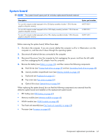
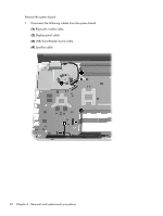
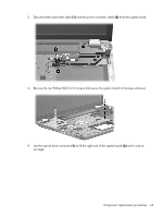
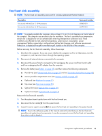
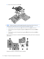
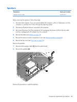
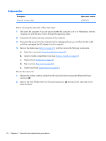
Fan/heat sink assembly NOTE: The fan/heat sink assembly spare part kit includes replacement thermal material. Description For use only with Intel Core i7, 45-W processors For use only with Intel Core i5, 35-W processors Spare part number 608650-001 603799-001 NOTE: To properly ventilate the computer, allow at least 7.6 cm (3 in) of clearance on the left side of the computer. The computer uses an electric fan for ventilation. The fan is controlled by a temperature sensor and is designed to turn on automatically when high temperature conditions exist. These conditions are affected by high external temperatures, system power consumption, power management/battery conservation configurations, battery fast charging, and software requirements. Exhaust air is displaced through the ventilation grill located on the left side of the computer. Before removing the fan/heat sink assembly, follow these steps: 1. Shut down the computer. If you are unsure whether the computer is off or in Hibernation, turn the computer on, and then shut it down through the operating system. 2. Disconnect all external devices connected to the computer. 3. Disconnect the power from the computer by first unplugging the power cord from the AC outlet and then unplugging the AC adapter from the computer. 4. Remove the battery (see Battery on page 38), and then remove the following components: a. Hard drives (see Primary hard drive on page 39 and see Secondary hard drive on page 45) b. memory module compartment cover (see Memory module on page 43) c. Keyboard (see Keyboard on page 51) d. Top cover (see Top cover on page 53) e. Optical drive (see Optical drive on page 58) f. System board (see System board on page 61) Remove the fan/heat sink assembly: 1. Turn the system board upside down with the front toward you. 2. Disconnect the fan cable (1) from the system board. 3. Loosen the seven captive screws (2) that secure the fan/heat sink assembly to the system board. NOTE: Due to the adhesive quality of the thermal material located between the fan/heat sink assembly and system board components, it may be necessary to move the fan/heat sink assembly from side to side to detach it. Component replacement procedures 65
-
 1
1 -
2
-
3
-
4
-
5
-
6
-
7
-
8
-
9
-
10
-
11
-
12
-
13
-
14
-
15
-
16
-
17
-
18
-
19
-
20
-
21
-
22
-
23
-
24
-
25
-
26
-
27
-
28
-
29
-
30
-
31
-
32
-
33
-
34
-
35
-
36
-
37
-
38
-
39
-
40
-
41
-
42
-
43
-
44
-
45
-
46
-
47
-
48
-
49
-
50
-
51
-
52
-
53
-
54
-
55
-
56
-
57
-
58
-
59
-
60
-
61
-
62
-
63
-
64
-
65
-
66
-
67
-
68
-
69
-
 70
70 -
 71
71 -
 72
72 -
 73
73 -
 74
74 -
 75
75 -
 76
76 -
 77
77 -
 78
78 -
 79
79 -
 80
80 -
81
-
82
-
83
-
84
-
85
-
86
-
87
-
88
-
89
-
90
-
91
-
92
-
93
-
94
-
95
-
96
-
97
-
98
-
99
-
100
-
101
-
102
-
103
-
104
-
105
-
106
-
107
-
108
-
109
-
110
-
111
-
112
-
113
-
114
-
115
-
116
-
117
-
118
-
119
-
120
 |
 |
