HP ENVY 17-1100 HP ENVY 17 - Maintenance and Service Guide - Page 82
from the opening in the base enclosure.
 |
View all HP ENVY 17-1100 manuals
Add to My Manuals
Save this manual to your list of manuals |
Page 82 highlights
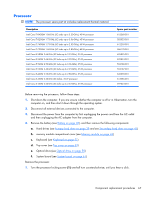
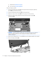
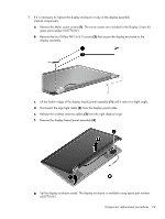
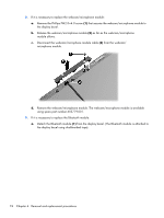
c. Keyboard (see Keyboard on page 51) d. Top cover (see Top cover on page 53) Remove the display assembly: 1. Disconnect the display panel cable (1) from the system board and release the cable from the clip (2) built into the base enclosure. 2. Disconnect the Bluetooth module cable (3) from the system board. 3. Release the wireless antenna cables (4) from the opening in the base enclosure. 4. Release the wireless antenna cables from the clips built into the base enclosure (5) and subwoofer (6). CAUTION: Support the display assembly when removing the following screws. Failure to support the display assembly can result in damage to the display assembly and other computer components. 5. Remove the four Phillips PM2.5×7.0 screws (1) that secure the display assembly to the computer. 6. Remove the display assembly (2). 72 Chapter 4 Removal and replacement procedures
-
 1
1 -
2
-
3
-
4
-
5
-
6
-
7
-
8
-
9
-
10
-
11
-
12
-
13
-
14
-
15
-
16
-
17
-
18
-
19
-
20
-
21
-
22
-
23
-
24
-
25
-
26
-
27
-
28
-
29
-
30
-
31
-
32
-
33
-
34
-
35
-
36
-
37
-
38
-
39
-
40
-
41
-
42
-
43
-
44
-
45
-
46
-
47
-
48
-
49
-
50
-
51
-
52
-
53
-
54
-
55
-
56
-
57
-
58
-
59
-
60
-
61
-
62
-
63
-
64
-
65
-
66
-
67
-
68
-
69
-
70
-
71
-
72
-
73
-
74
-
75
-
76
-
 77
77 -
 78
78 -
 79
79 -
 80
80 -
 81
81 -
 82
82 -
 83
83 -
 84
84 -
 85
85 -
 86
86 -
 87
87 -
88
-
89
-
90
-
91
-
92
-
93
-
94
-
95
-
96
-
97
-
98
-
99
-
100
-
101
-
102
-
103
-
104
-
105
-
106
-
107
-
108
-
109
-
110
-
111
-
112
-
113
-
114
-
115
-
116
-
117
-
118
-
119
-
120
 |
 |
