HP ENVY 17-1100 HP ENVY 17 - Maintenance and Service Guide - Page 71
System board, When replacing the system board
 |
View all HP ENVY 17-1100 manuals
Add to My Manuals
Save this manual to your list of manuals |
Page 71 highlights
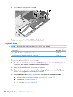
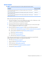
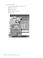
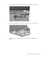
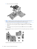
System board NOTE: The system board spare part kit includes replacement thermal material. Description For use with computer models equipped with a 3D display assembly (includes 1 GB of discrete graphics subsystem memory) For use with computer models equipped with an FHD display assembly (includes 1 GB of discrete graphics subsystem memory) For use with computer models equipped with an HD+ display assembly (includes 1 GB of discrete graphics subsystem memory) Spare part number 620774-001 618859-001 603771-001 Before removing the system board, follow these steps: 1. Shut down the computer. If you are unsure whether the computer is off or in Hibernation, turn the computer on, and then shut it down through the operating system. 2. Disconnect all external devices connected to the computer. 3. Disconnect the power from the computer by first unplugging the power cord from the AC outlet and then unplugging the AC adapter from the computer. 4. Remove the battery (see Battery on page 38), and then remove the following components: a. Hard drives (see Primary hard drive on page 39 and see Secondary hard drive on page 45) b. memory module compartment cover (see Memory module on page 43) c. Keyboard (see Keyboard on page 51) d. Top cover (see Top cover on page 53) e. Optical drive (see Optical drive on page 58) When replacing the system board, be sure that the following components are removed from the defective system board and installed on the replacement system board: ● RTC battery (see RTC battery on page 42) ● Memory modules (see Memory module on page 43) ● WLAN module (see WLAN module on page 49) ● Fan/heat sink assembly (see Fan/heat sink assembly on page 65) ● Processor (see Processor on page 67) Component replacement procedures 61
-
 1
1 -
2
-
3
-
4
-
5
-
6
-
7
-
8
-
9
-
10
-
11
-
12
-
13
-
14
-
15
-
16
-
17
-
18
-
19
-
20
-
21
-
22
-
23
-
24
-
25
-
26
-
27
-
28
-
29
-
30
-
31
-
32
-
33
-
34
-
35
-
36
-
37
-
38
-
39
-
40
-
41
-
42
-
43
-
44
-
45
-
46
-
47
-
48
-
49
-
50
-
51
-
52
-
53
-
54
-
55
-
56
-
57
-
58
-
59
-
60
-
61
-
62
-
63
-
64
-
65
-
 66
66 -
 67
67 -
 68
68 -
 69
69 -
 70
70 -
 71
71 -
 72
72 -
 73
73 -
 74
74 -
 75
75 -
 76
76 -
77
-
78
-
79
-
80
-
81
-
82
-
83
-
84
-
85
-
86
-
87
-
88
-
89
-
90
-
91
-
92
-
93
-
94
-
95
-
96
-
97
-
98
-
99
-
100
-
101
-
102
-
103
-
104
-
105
-
106
-
107
-
108
-
109
-
110
-
111
-
112
-
113
-
114
-
115
-
116
-
117
-
118
-
119
-
120
 |
 |
