HP EliteBook 650 Maintenance and Service Guide - Page 65
Fan, Reverse this procedure to install the smart card reader.
 |
View all HP EliteBook 650 manuals
Add to My Manuals
Save this manual to your list of manuals |
Page 65 highlights
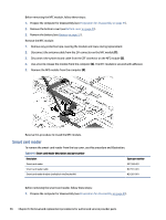
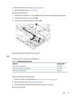
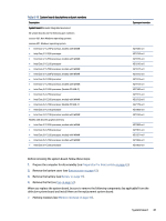
2. Remove the bottom cover (see Bottom cover on page 41). 3. Remove the battery (see Battery on page 51). Remove the smart card reader: 1. Remove the four Phillips M2.0 × 2.0 screws (1) from the metal bracket covering the card reader board. 2. Disconnect the cable from the card reader (2). 3. Lift the smart card reader straight up to remove it (3). Fan Reverse this procedure to install the smart card reader. To remove the fan, use this procedure and illustration. Table 6-7 Fan description and part number Description Fan for use in 42 W, UMA models Fan for use in models with discrete graphics Fan for use in 51 W, UMA models Spare part number M21718-001 M21719-001 N00095-001 Before removing the fan, follow these steps: 1. Prepare the computer for disassembly (see Preparation for disassembly on page 41). 2. Remove the bottom cover (see Bottom cover on page 41). 3. Disconnect the battery cable from the system board (see Battery on page 51). Remove the fan assembly: Fan 57
-
 1
1 -
2
-
3
-
4
-
5
-
6
-
7
-
8
-
9
-
10
-
11
-
12
-
13
-
14
-
15
-
16
-
17
-
18
-
19
-
20
-
21
-
22
-
23
-
24
-
25
-
26
-
27
-
28
-
29
-
30
-
31
-
32
-
33
-
34
-
35
-
36
-
37
-
38
-
39
-
40
-
41
-
42
-
43
-
44
-
45
-
46
-
47
-
48
-
49
-
50
-
51
-
52
-
53
-
54
-
55
-
56
-
57
-
58
-
59
-
 60
60 -
 61
61 -
 62
62 -
 63
63 -
 64
64 -
 65
65 -
 66
66 -
 67
67 -
 68
68 -
 69
69 -
 70
70 -
71
-
72
-
73
-
74
-
75
-
76
-
77
-
78
-
79
-
80
-
81
-
82
-
83
-
84
-
85
-
86
-
87
-
88
-
89
-
90
-
91
-
92
-
93
-
94
-
95
-
96
-
97
-
98
-
99
-
100
-
101
-
102
-
103
-
104
-
105
-
106
-
107
-
108
-
109
-
110
-
111
 |
 |
