HP EliteBook 650 Maintenance and Service Guide - Page 73
Display assembly
 |
View all HP EliteBook 650 manuals
Add to My Manuals
Save this manual to your list of manuals |
Page 73 highlights
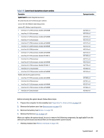
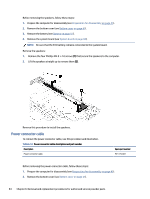
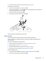
3. Disconnect the battery cable from the system board (see Battery on page 51). Remove the power connector cable: 1. Remove the antenna cables that route over the screws (1). 2. Remove the three Phillips M2.5 × 4.0 screws (2) that secure the right display hinge to the computer, and then rotate the hinge off the power connector (3). 3. Disconnect the cable from the system board (4). 4. Remove the power connector cable from the computer (5). Reverse this procedure to install the power connector cable. Display assembly To remove and disassemble the display assembly, use these procedures and illustrations. Full hinge-up displays are not available as spare parts. Spare parts for displays are available only at the subcomponent level. Before removing the display panel, follow these steps: 1. Prepare the computer for disassembly (see Preparation for disassembly on page 41). 2. Remove the bottom cover (see Bottom cover on page 41). 3. Disconnect the battery cable from the system board (see Battery on page 51). 4. Remove the power connector cable (see Power connector cable on page 64). Remove the display assembly: 1. Disconnect the display cable (1), and then remove the cable from the clips around the fan (2). 2. Disconnect the antenna cables from the WLAN module (3). Display assembly 65
-
 1
1 -
2
-
3
-
4
-
5
-
6
-
7
-
8
-
9
-
10
-
11
-
12
-
13
-
14
-
15
-
16
-
17
-
18
-
19
-
20
-
21
-
22
-
23
-
24
-
25
-
26
-
27
-
28
-
29
-
30
-
31
-
32
-
33
-
34
-
35
-
36
-
37
-
38
-
39
-
40
-
41
-
42
-
43
-
44
-
45
-
46
-
47
-
48
-
49
-
50
-
51
-
52
-
53
-
54
-
55
-
56
-
57
-
58
-
59
-
60
-
61
-
62
-
63
-
64
-
65
-
66
-
67
-
 68
68 -
 69
69 -
 70
70 -
 71
71 -
 72
72 -
 73
73 -
 74
74 -
 75
75 -
 76
76 -
 77
77 -
 78
78 -
79
-
80
-
81
-
82
-
83
-
84
-
85
-
86
-
87
-
88
-
89
-
90
-
91
-
92
-
93
-
94
-
95
-
96
-
97
-
98
-
99
-
100
-
101
-
102
-
103
-
104
-
105
-
106
-
107
-
108
-
109
-
110
-
111
 |
 |
