HP J8697A User Manual
HP J8697A Manual
 |
View all HP J8697A manuals
Add to My Manuals
Save this manual to your list of manuals |
HP J8697A manual content summary:
- HP J8697A | User Manual - Page 1
Installation and Getting Started Guide ProCurve Series 5400zl Switches PoE Power over Ethernet Devices www.procurve.com - HP J8697A | User Manual - Page 2
- HP J8697A | User Manual - Page 3
ProCurve Series 5400zl Switches Installation and Getting Started Guide - HP J8697A | User Manual - Page 4
-Packard. Publication Number 5991-4741 February 2007 Applicable Products ProCurve Switch 5406zl ProCurve Switch 5406zl-48G ProCurve Switch 5412zl ProCurve Switch 5412zl-96G ProCurve Switch zl Power Supply Shelf (J8697A) (J8699A) (J8698A) (J8700A) (J8714A) Disclaimer HEWLETT-PACKARD COMPANY MAKES - HP J8697A | User Manual - Page 5
Contents 1 Introducing the ProCurve Series 5400zl Switches Front of the Switch 1-5 LEDs 1-6 LED Mode Select Button and Indicator LEDs 1-9 Console Port 1-10 Reset Button 1-10 Clear Button 1-10 Back of the Switch 1-11 Power Connector 1-12 Redundant Power Supply 1-12 Switch Features 1-13 2 - HP J8697A | User Manual - Page 6
the IP Address for Remote Switch Management 3-5 Starting a Telnet Session 3-5 Starting a Web Browser Session 3-5 4 Replacing Components Replacing Power Supplies 4-2 Replacing Fan Trays 4-4 Replacing the Management Module 4-5 Replacing the Management Module Compact Flash Card 4-6 Installing - HP J8697A | User Manual - Page 7
11 Testing End-to-End Network Communications 5-11 Restoring the Factory Default Configuration 5-12 Downloading New Code 5-13 HP Customer Support Services 5-13 Before Calling Support 5-13 A Specifications Physical A-1 Electrical A-1 Environmental A-2 Acoustic A-3 Switch 5400zl and 5406zl-48G - HP J8697A | User Manual - Page 8
Cables B-2 Twisted-Pair B-2 Fiber-Optic Cables B-3 Copper Cables B-4 Mode Conditioning Patch Cord for Gigabit-LX B-5 Installing the Patch Cord B-6 Twisted-Pair Cable/Connector Pin-Outs B-6 Straight-Through Twisted-Pair Cable for 10 Mbps or 100 Mbps Network Connections B-8 Cable Diagram B-8 - HP J8697A | User Manual - Page 9
D Recycle Statements Waste Electrical and Electronic Equipment (WEEE) Statements D-1 Index vii - HP J8697A | User Manual - Page 10
- HP J8697A | User Manual - Page 11
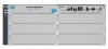
slot chassis (J8697A) and as the Switch 5406zl-48G bundle (J8699A) with two 24-port 10/100/1000-T zl Modules pre-installed. The open 6-slot chassis (J8697A) does not ship with any power supplies. The switch needs at least one power supply to operate. Figure 1-1. ProCurve Switch 5406zl (J8697A) 1-1 - HP J8697A | User Manual - Page 12
Introducing the ProCurve Series 5400zl Switches Introducing the ProCurve Series 5400zl Switches Note The 5406zl-48G bundle (J8699A) does ship with one power supply, the J8712A. Figure 1-2. ProCurve Switch 5406zl-48G bundle (J8699A) with two 10/100/1000-T zl Modules 1-2 - HP J8697A | User Manual - Page 13
Introducing the ProCurve Series 5400zl Switches Switch 5412zl, Switch 5412zl-96G. The Switch 5412zl is available as an open 12-slot chassis (J8698A) and as the Switch 5412zl-96G bundle (J8700A) with four 24-port 10/100/1000-T zl Modules pre-installed. Figure 1-3. ProCurve Switch 5412zl (J8698A - HP J8697A | User Manual - Page 14
two power supplies, the J8712A. Introducing the ProCurve Series 5400zl Switches Figure 1-4. ProCurve Switch 5412zl-96G (J8700A) See "Switch Features" on page 1-13 for a list of the switch modules that can be installed in the ProCurve Series 5400zl Switches (modules available when this manual was - HP J8697A | User Manual - Page 15
Introducing the ProCurve Series 5400zl Switches Introducing the ProCurve Series 5400zl Switches Front of the Switch Front of the Switch Power and Fault LEDs Locator LED Status LEDs for the Fans, Power Supplies, and Switch Modules Reset and Clear buttons LED Mode Select button and indicator LEDs - HP J8697A | User Manual - Page 16
State Meaning On The switch is receiving power. Off The switch is NOT receiving power. Off The normal state; indicates that there are no fault conditions on the switch. Blinking1 A fault has occurred on the switch, one of the switch modules, an individual port, a power supply, or a fan. The - HP J8697A | User Manual - Page 17
the ProCurve Series 5400zl Switches Introducing the ProCurve Series 5400zl Switches Front of the Switch LEDs State Meaning Mgmt (green/Orange) On A Management module is present and fault free. Off The switch is powered off. Blinking1 There is a fault on the Management module. PoE - HP J8697A | User Manual - Page 18
light • the port has been disabled through the switch console, the web browser interface, ProCurve Manager, or other network management tool. The port has failed self test. The switch Fault, Self Test LEDs, and appropriate module status LEDs will flash simultaneously. Mode Depending on the - HP J8697A | User Manual - Page 19
Introducing the ProCurve Series 5400zl Switches Introducing the ProCurve Series 5400zl Switches Front of the Switch LED Mode Select Button and Indicator LEDs To optimize the amount of information that can be displayed for each of the switch ports, the Series 5400zl Switches use a Mode LED for each - HP J8697A | User Manual - Page 20
browser interface, and through SNMP network management applications, such as ProCurve Manager. Press the Reset button also after changing the module type that is installed in any of the switch module slots while the switch is powered on. In this case, the switch must be reset to initialize the new - HP J8697A | User Manual - Page 21
specific method to restore the factory default configuration, see "Restoring the Factory Default Configuration" in chapter 4, "Troubleshooting" of this manual. Back of the Switch . AC power connector Grounding lug mounting holes Slot for installing optional redundant power supply Power and Fault - HP J8697A | User Manual - Page 22
one power supply will only supply enough power to run the module slots A-F. Slots G-L will not receive any power unless there are at least two power supplies installed. For more information regarding power see the: ■ ProCurve Switch zl Internal Power Supply Installation Guide. ■ ProCurve Power over - HP J8697A | User Manual - Page 23
on PoE power refer to the ProCurve PoE Planning and Implementation Guide. For more information on the J8702A module refer to the ProCurve Switch zl Modules Installation Guide. • 20-port Gig-T and 4-port mini-GBIC/SFP zl PoE Module (J8705A)-- into which you can install the supported mini-GBICs - HP J8697A | User Manual - Page 24
through an intuitive menu interface. • ProCurve Manager-an SNMP-based graphical interface that is used to manage your entire network, included with your new switch. • Supported by ProCurve Network Manager-an HP OpenView application that accurately displays your switch on network maps and provides - HP J8697A | User Manual - Page 25
have the following components shipped with them: ■ ProCurve Series 5400zl Switches Installation and Getting Started Guide, this manual ■ ProCurve Manager - CD ROM and booklet ■ Customer Support/Warranty booklet ■ Accessory kits 5406zl Accessory Kit (5069-8561) 5412zl Accessory Kit (5069-8562 - HP J8697A | User Manual - Page 26
Installing the Series 5400zl Switches Included Parts Region Australia/New Zealand China Continental Europe Denmark Japan Switzerland United Kingdom/ Hong Kong 8120-6897 8120-6898 8120-6903* 8121-0915 8120-6903 8121-1010 8121-0675 Japan Power Cord Warning Installing the Series 5400zl Switches 2-2 - HP J8697A | User Manual - Page 27
the switch is powered on. Make sure you use only ProCurve Switch zl Modules in your Series 5400zl Switches. 3. Install power supplies (page 2-12). The Series 5406zl Switches supports up to two power supplies. It may be easier to install the power supplies before mounting the switch. The switch must - HP J8697A | User Manual - Page 28
it in to the nearby main power source. 8. Connect a Power Supply Shelf (optional-page 2-22). You may wish to use a Power Supply Shelf with your switch. To do so you must connect the external power supply using the EPS cables supplied with the Power Supply Shelf. 9. Connect the network devices (page - HP J8697A | User Manual - Page 29
a cover plate is installed on any empty switch power supply or module slot. A cover plate is required for safe operation, and to ensure proper switch cooling. Never have more than one power supply or module slot uncovered at a time while the switch is powered on. ■ To avoid energy and mechanical - HP J8697A | User Manual - Page 30
is to be shipped in a rack, use only an HP 10000 series rack and a rail mounting kit (5070-0145) for each switch. ■ Ensure the power source circuits are properly grounded, then use the power cord supplied with the switch to connect it to the power source. ■ If your installation requires a different - HP J8697A | User Manual - Page 31
-T zl Modules and 100/1000-T Transceiver are compatible with the IEEE 802.3ab standard including the "Auto MDI/MDI-X" feature, which allows use either straight-through or crossover twisted-pair cables for connecting to any network devices including end nodes, such as computers, or to other switches - HP J8697A | User Manual - Page 32
specification). Note: Conditioning patch cord cables are not supported switch, allow at least 7.6 cm (3 inches) of space for the twisted-pair and fiber-optic cabling. ■ In the back of the switch, allow at least 10.2 cm (4 inches) of space for the power cord and cooling. ■ On the sides of the switch - HP J8697A | User Manual - Page 33
shown in the illustration below. For installation details, see the instructions in the manual that comes with the module. Make sure you install only ProCurve Switch zl Modules. Avoid any electrostatic discharge problems by handling the modules only by their bulkheads. The slot cover can be removed - HP J8697A | User Manual - Page 34
Installing the Series 5400zl Switches Installing the Series 5400zl Switches Installation Procedures Insert module into the guides and slide it in until it is fully inserted. Open extractor handles Figure 2-1. Module Being Installed in a Chassis 2-10 - HP J8697A | User Manual - Page 35
Use the extractor handles to seat the module completely. Installing the Series 5400zl Switches Installation Procedures Then tighten the retaining screws on the module until they are secure, but do not overtighten them. Figure 2-2. Generic Chassis with Module Fully Installed Installing the Series - HP J8697A | User Manual - Page 36
supply (either a ProCurve Switch zl 875 W Power Supply (J8712A), or a ProCurve Switch zl 1500 W Power Supply (J8713A) can be installed in the back of the switch. The 5406zl can hold up to two power supplies and the 5412zl can hold up to four power supplies. The 875 W Power Supply (J8712A) can supply - HP J8697A | User Manual - Page 37
" on page 2-6 for more information. For installation details, see the instructions in the manual that comes with the power supply. Insert the power supply into the opening, then slide it all the way in until it connects to the switch. The power supply face plate will be flush with the back face of - HP J8697A | User Manual - Page 38
Once the power supply is installed, tighten the four retaining screws that hold it in place. The screws can be tightened with either a flat-bladed or Torx T-10 screwdriver. Be careful not to overtighten the screws. tighten the four screws Figure 2-4. Back of Switch with Power Supply Fully Installed - HP J8697A | User Manual - Page 39
power cord than the one supplied with the switch, please see the "Installation Precautions" on page 2-6. 2. Check the LEDs on the switch and on each of the switch modules. The LED behavior is described on the next page. If the LED display is different than what is described, especially if the Fault - HP J8697A | User Manual - Page 40
, and the Status LEDs on the switch chassis stay on for the devices installed: one for each switch module installed, one for each power supply installed, and one for all the fans. ■ The Fault, Locator, and Test LEDs are off. ■ The port LEDs on the switch modules go into their normal operational mode - HP J8697A | User Manual - Page 41
the mode selected. In the default mode (Activity), the Mode LEDs should flicker showing network activity on the port. • If the ports are not connected to active network devices, the LEDs will stay off. 5.Mount the Switch After the modules and optional power supply are installed and you have verified - HP J8697A | User Manual - Page 42
mm M4 screws Figure 2-7. Attaching Brackets to the 5400zl Switch 2. Partially install a screw into the top hole of (0.5-inch) pair on both sides of the rack Figure 2-8. Mounting Screw Positioning 3. Place the switch in the rack and lower it so the notches in the bottom of the bracket slide onto the - HP J8697A | User Manual - Page 43
lower the switch with mounting brackets onto the partially installed screws, then tighten these screws Installing the Series 5400zl Switches Installation Procedures Figure 2-9. Notches in Bracket Being Installed Installing the Series 5400zl Switches 2-19 - HP J8697A | User Manual - Page 44
on a table or other horizontal surface. Use a sturdy surface in an uncluttered area. You may want to secure the networking cables and switch power cord to the table legs or other part of the surface structure to help prevent people from tripping over the cords. Ensure the air flow - HP J8697A | User Manual - Page 45
to power one switch power supply from the regular AC source, and the other power supply from the redundant AC source. This will provide redundancy in AC power to the switch, as long as the switch PoE power usage falls within the capability of one power supply. If both power supplies are plugged - HP J8697A | User Manual - Page 46
PoE power supply should fail, or as additional PoE power to be made available to the switch's PoE ports. For further information regarding the EPS PoE capabilities, see the ProCurve Power over Ethernet (PoE) for zl and yl Products Planning and Implementation Guide and the ProCurve Power Supply Shelf - HP J8697A | User Manual - Page 47
the end devices connected to the switch ports may not receive power if an internal switch PoE power supply should fail. For further information regarding the Power Supply Shelf PoE capabilities, see the ProCurve Power over Ethernet (PoE) for zl and yl Products Planning and Implementation Guide and - HP J8697A | User Manual - Page 48
the Series 5400zl Switches Installation Procedures Connecting the Power Supply Shelf To Power Source To Power Source Installing the Series 5400zl Switches 5406zl EPS Cables Figure 2-12. Connecting the EPS to one 5406zl switch To Power Source To Power Source 5406zl 5406zl EPS Cables Figure - HP J8697A | User Manual - Page 49
match. Mismatched configurations are a frequent cause of connection problems. You can use the console interface, or, if you have configured an IP address on the switch, use the web browser interface, or ProCurve Manager network management software to determine the state and configuration of the - HP J8697A | User Manual - Page 50
troubleshooting ■ Download new software to the switch ■ Add passwords and other security features to control access to the switch from the console, web browser interface, and network management through DHCP/Bootp. The Series 5400zl Switches can simultaneously support one out-of-band console session - HP J8697A | User Manual - Page 51
to the PC end of the console cable.) console port console cable supplied with the switch 2. Turn on the terminal or PC's power and, if Switch Configuration" for some basic configuration steps. For more detailed information, refer to the Management and Configuration Guide which is on the ProCurve - HP J8697A | User Manual - Page 52
two power supplies are installed, both power cords would have to be unplugged. ■ Issuing the boot command from the switch console CLI, or selecting the boot Switch option from the switch console menu, the web browser interface, or ProCurve Manager. Until the switch is rebooted, the module will not - HP J8697A | User Manual - Page 53
slot chassis, the principles are the same for the 12-slot chassis. Basic Connectivity Series 5400zl Switch Phones, APs and other peripherals Figure 2-15. Basic Switch Connectivity The Series 5400zl Switches can provide basic network connectivity to a high number of PoE devices. These devices can be - HP J8697A | User Manual - Page 54
a ProCurve Routing Switch 9308, which can serve as a campus backbone or core switch. The 1000 Mbps fiber-optic connections between the two Switch 5406zls and the Routing Switch 9308 is by way of Gigabit-LX mini-GBICs installed in the mini-GBIC port on the 20 port Gig-T plus 4 mini-GBIC zl Module in - HP J8697A | User Manual - Page 55
management tool, ProCurve Manager, please see the Management and Configuration Guide which is on the ProCurve Web site. See page 5-1 for details. Recommended Minimal Configuration In the factory default configuration, the switch has no IP (Internet Protocol) address and subnet mask, and no passwords - HP J8697A | User Manual - Page 56
of the manual method described in this chapter, see "DHCP/Bootp Operation" in the Management and Configuration Guide which is on the ProCurve Web site. See page 5-1 for details. Using the Switch Setup Screen The quickest and easiest way to minimally configure the switch for management and password - HP J8697A | User Manual - Page 57
and Configuration Guide which is on the ProCurve Web site. See page 5-1 for details. Parameter Default System Name blank Optional; up to 25 characters, including spaces System Contact blank Optional; up to 48 characters, including spaces Manager Password blank Recommended; up to 16 - HP J8697A | User Manual - Page 58
on the Series 5400zl Switches, please see the Management and Configuration Guide which is on the ProCurve Web site. See page 5-1 for details. To Recover from a Lost Manager Password: If you cannot start a console session at the manager level because of a lost Manager password, you can clear all - HP J8697A | User Manual - Page 59
the copyright page and the message "Press any key to continue". Press a key, and you will then see the switch console command (CLI) prompt, for example (assuming there is no password): ProCurve 5400zl# Enter help or ? to see a list of commands that can be executed at the prompt. Entering any command - HP J8697A | User Manual - Page 60
Switch 5406zl - Sxtlatus: Information J8699A ProCurve Switch 5406xzl ll PoE Status Getting Started With Switch Configuration Figure 3-2. Switch Web Browser Interface - Status Overview For more information on using the web browser interface, please see the Management and Configuration Guide - HP J8697A | User Manual - Page 61
page 2-1. Hot Swapping The ProCurve Switch 5400zl supports "hot swapping" - the ability to replace the following hardware components while the switch is operating: a fan tray, power supply (if a second power supply is installed), interface module. The Management module and its components are not - HP J8697A | User Manual - Page 62
Supplies Replacing Power Supplies If your ProCurve 5400zl Switch is configured with redundant power supplies, you will not suffer any loss of traffic or performance if a power supply fails. Replace the failed component as soon as possible. One of the Internal Power LEDs on the management module - HP J8697A | User Manual - Page 63
face of the switch. tighten the four screws Figure 4-2. Power Supply Installation 4. Tighten the four retaining screws that hold it in place. Be careful not to overtighten the screws. For more detail refer to the ProCurve Switch zl Internal Power Supply Installation Guide (5991-3787). 4-3 Replacing - HP J8697A | User Manual - Page 64
chassis will blink simultaneously with the switch Fault LED. In this case, the entire fan tray needs to be replaced. You cannot replace individual fans. The fan tray is hot swappable. It can be removed and replaced without removing power from the switch. However, install the new fan tray immediately - HP J8697A | User Manual - Page 65
Replacing the Management Module Replacing the Management Module The switch does not have to be powered off to remove the management module, however when the management module is removed all ports will lose communication. ProCurve Networking recommends replacing the Management module, flash disk - HP J8697A | User Manual - Page 66
primary non-volatile storage medium located on the management module that contains both the boot software and configuration files. When a Flash card fails the Flash status LED on the management module will blink simultaneously with the switch Fault LED. Installing a Compact Flash Card To install (or - HP J8697A | User Manual - Page 67
The battery on the management module is used to keep time for the internal switch clock. There is no indicator LED for when the battery dies. The only indication will be the internal clock will not keep the correct time. ■ The battery requires special handling at end-of-life. The battery can explode - HP J8697A | User Manual - Page 68
the management module into the switch. 6. Use an equal amount of pressure and push both extractor handles closed to completely seat the module. 7. constructeur. Mettre au rebut les batteries usagées conformément aux instructions du fabricant. ATTENTION If this product contains a real-time clock - HP J8697A | User Manual - Page 69
information, see the chapter "Troubleshooting" in the Management and Configuration Guide, which is on the ProCurve Web site at www.procurve.com. To display the list of downloadable manuals, click on the following links: Technical support Product manuals (all) ProCurve Switch 3500yl or 6200yl Series - HP J8697A | User Manual - Page 70
, the web browser interface, or ProCurve Manager. The Series 5400zl Switches also support Trunking, which allows multiple network cables to be used for a single network connection without causing a data path loop. See the Management and Configuration Guide for more information on Spanning Tree - HP J8697A | User Manual - Page 71
any of the switch features that may be affecting the port. See the Management and Configuration Guide which is on the ProCurve Web site. See page 5-1 for details. For more information on possible network problems and their solutions, refer to the technical note "Troubleshooting LAN Performance and - HP J8697A | User Manual - Page 72
Troubleshooting Power Fault Test Module Status (one LED per module) Power (one LED per power supply) Fan Port Link Troubleshooting Diagnosing with the LEDs Diagnosing with the LEDs Table 5-1 shows LED patterns on the switch and the switch modules that indicate problem conditions. 1. Check in the - HP J8697A | User Manual - Page 73
, the switch power supply may have failed. Call your ProCurve authorized LAN dealer, or use the electronic support services from ProCurve to get assistance. See the Customer Support/Warranty card for more information. ➋ A switch hardware Try power cycling the switch. If the fault indication - HP J8697A | User Manual - Page 74
the printing of this manual, are listed on page 1-13 under "Switch Features". The latest code can be downloaded from the ProCurve Networking Web site at www.procurve.com. First verify the switch has a version of code that supports the module that is indicating the fault. If the module is not one of - HP J8697A | User Manual - Page 75
, the power supply may be faulty. Call your ProCurve authorized LAN dealer, or use the electronic support services from ProCurve number. Networking to get assistance. See the Customer Support/Warranty card for more information. ➒ One or more of the Try disconnecting power from the switch and - HP J8697A | User Manual - Page 76
or, if you have configured an IP address on the switch, use the web browser interface, or ProCurve Manager network management software to determine the state of the port and re-enable the port if necessary. • Verify the switch port configuration matches the configuration of the attached device. For - HP J8697A | User Manual - Page 77
. The console interface is also accessible through a telnet connection. See the "Troubleshooting" chapter in the Management and Configuration Guide for more information on using these software tools to diagnose and manage your switch, which is on the ProCurve Web site. See page 5-1 for details. 5-9 - HP J8697A | User Manual - Page 78
, web browser interface, or ProCurve Manager. Power cycling the switch, pressing the Reset button, and the software reset or reboot options all cause the switch to perform its power-on self-test, which almost always will resolve any temporary operational problems. These reset processes also cause - HP J8697A | User Manual - Page 79
. See the Management and Configuration Guide which is on the ProCurve Web site. See page 5-1 for details. These tests can also be performed from an SNMP network management station running a program that can manage the switch, for example, ProCurve Manager. Testing End-to-End Network Communications - HP J8697A | User Manual - Page 80
factory default reset. Then, after the reset and resolution of the original problem, you can restore the saved configuration to the switch. For both the save and restore processes, you can use the console copy command. See the switch Management and Configuration Guide which is on the ProCurve Web - HP J8697A | User Manual - Page 81
Please see the Management and Configuration Guide which is on the ProCurve Web site. See page 5-1 for details. The new code would be available on the ProCurve Networking Web site, www.procurve.com. HP Customer Support Services If you are still having trouble with your switch, Hewlett-Packard offers - HP J8697A | User Manual - Page 82
- HP J8697A | User Manual - Page 83
Depth: Height: • Switch 5406zl • Switch 5412zl Weight: • Switch 5406zl • Switch 5406zl-48G • Switch 5412zl • Switch 5412zl-96G 44.2 cm (17.4 in) 45.0 cm (17.7 in) 17.5 cm (6.8 in) 30.74 cm (12.1 in) • 10.68 kg (23.55 lbs) • 15.54 kg (34.25 lbs) - includes two modules and one power supply • 15.86 kg - HP J8697A | User Manual - Page 84
4.6 km (15,000 ft) 1 If you are installing either the J8705A or J8707A modules, or any of the X2 transceivers, the operating ambient temperature should not exceed 40°C (104°F). See transceiver specifications below. TRANSCEIVERS Temperature: SR Optic J8436A LR Optic J8437A ER Optic J8438A Copper - HP J8697A | User Manual - Page 85
Specifications Running H/F 1 Acoustic Switch 5400zl and 5406zl-48G: Geräuschemission LpA = 40.2 dB am fiktiven Arbeitsplatz nach DIN 45635 T.19 Noise Emission LpA = 40.2 dB in a virtual workspace according to DIN 45635 T.19 Switch ports on the 100/1000-T zl Module are compatible with the IEEE 802.3u - HP J8697A | User Manual - Page 86
Specifications Lasers The following products are Class 1 Laser Products. ■ Laser Klasse 1:The 10-GbE X2-SC SR transceiver ■ The 10-GbE X2-SC LR products are Class 1m Laser Products. Laser Klasse 1m: ■ The 10-GbE X2 SR-SC transceiver The transceivers comply with IEC 60825. Specifications A-4 - HP J8697A | User Manual - Page 87
cable information for cables that should be used with the Series 5400zl Switches, including minimum pin-out information and specifications for twisted-pair cables. Incorrectly wired cabling is the most common cause of problems for LAN communications. It is recommended that you work with a qualified - HP J8697A | User Manual - Page 88
ohm differential UTP or STP cable, complying with IEEE 802.3u 100Base-TX specifications, fitted with RJ-45 connectors. 1000 Mbps Operation Category 5 100-ohm cabling, be sure to include the patch cables that connect the switch and other end devices to the patch panels on your site. The patch cables - HP J8697A | User Manual - Page 89
Switch Ports and Network Cables Fiber-Optic Cables Port Type Gigabit-SX Gigabit-LX Gigabit-LH 10-GbE SR 10-GbE LR Cable Specifications Connector conditioning patch cord may be needed - See the Installation Guide that came with your module for more information. 9/125 μm (core/cladding) diameter, - HP J8697A | User Manual - Page 90
diameter, multimode Fiber ribbon cable is also supported. Optical Media Converter 1-300 meters Copper Cables Port Type CX4 Cable Specifications Speed 3.125Gbx4 (Cables compliant with the 802.3ak standard) Connector Type CX4 Supported Length 0.5-15 meters Switch Ports and Network Cables B-4 - HP J8697A | User Manual - Page 91
operation. Mode Conditioning Patch Cord cables are not supported for 10 Gigabit operation. Unlike Gigabit-SX, which -LX port in your switch and your multimode fiberoptic network cabling, and between the other end of the multimode fiber-optic cable run. A patch cord must be installed at both ends. The - HP J8697A | User Manual - Page 92
HP Auto-MDIX Feature. In the default configuration, "Auto", the 10/100Base-TX ports on the 10/100-TX and PoE xl Modules used in the Series 5400zl Switches all for any of the connections. The 100/1000-T xl Module supports the IEEE 802.3ab standard, which includes the "Auto MDI/MDI-X" feature, which - HP J8697A | User Manual - Page 93
HP Auto-MDIX and the IEEE 802.3ab Auto MDI/ MDI-X feature are completely compatible. If you connect a Series 5400zl Switch twisted-pair port to another switch end nodes, use a straight-through cable; for connections to MDIX ports, such as on hubs and other switches ) cable, as supported by the IEEE - HP J8697A | User Manual - Page 94
-Pair Cable for 10 Mbps or 100 Mbps Network Connections Because of the HP Auto-MDIX operation of the 10/100 ports on the switches, for all network connections, to PCs, servers or other end nodes, or to hubs or other switches, you can use straight-through cables. If any of these ports are - HP J8697A | User Manual - Page 95
for 10 Mbps or 100 Mbps Network Connection The HP Auto-MDIX operation of the 10/100 ports on the switches also allows you to use crossover cables for all network connections, to PCs, servers or other end nodes, or to hubs or other switches. If any of these ports are given a fixed configuration - HP J8697A | User Manual - Page 96
Twisted-Pair Cable for 1000 Mbps Network Connections 1000Base-T connections require that all four pairs or wires be connected. Cable Diagram Switch Ports and Network Cables Note . B-10 Figure B-4. Straight-through Cable Diagram for 1000 Mbps Network Connection Pins 1 and 2 on connector "A" must - HP J8697A | User Manual - Page 97
of the network with Caution. Servicing There are no user-serviceable parts inside these products. Any servicing, adjustment, maintenance, or repair must be performed only by service-trained personnel. These products do not have a power switch; they are powered on when the power cord is plugged in - HP J8697A | User Manual - Page 98
Safety and Regulatory Statements Informations concernant la sécurité Informations concernant la sécurité ! WARNING Caution Symbole de référence à la documentation. Si le produit est marqué de ce symbole, reportez-vous à la documentation du produit afin d'obtenir des informations plus détaillées. - HP J8697A | User Manual - Page 99
Safety and Regulatory Statements Hinweise zur Sicherheit Hinweise zur Sicherheit ! WARNING Caution Symbol für Dokumentationsverweis. Wenn das Produkt mit diesem Symbol markiert ist, schlagen Sie bitte in der Produktdokumentation nach, um mehr Informationen über das Produkt zu erhalten. Symbol für - HP J8697A | User Manual - Page 100
Safety and Regulatory Statements Considerazioni sulla sicurezza Considerazioni sulla sicurezza ! WARNING Caution Simbolo di riferimento alla documentazione. Se il prodotto è contrassegnato da questo simbolo, fare riferimento alla documentazione sul prodotto per ulteriori informazioni su di esso. - HP J8697A | User Manual - Page 101
Safety and Regulatory Statements Consideraciones sobre seguridad Consideraciones sobre seguridad ! WARNING Caution Símbolo de referencia a la documentación. Si el producto va marcado con este símbolo, consultar la documentación del producto a fin de obtener mayor información sobre el producto. - HP J8697A | User Manual - Page 102
Safety and Regulatory Statements Safety Information (Japan) Safety Information (Japan) C-6 Safety and Regulatory Statements - HP J8697A | User Manual - Page 103
Safety and Regulatory Statements Safety Information (China) Safety Information (China) C-7 Safety and Regulatory Statements - HP J8697A | User Manual - Page 104
environment. This equipment generates, uses, and can radiate radio frequency energy and, if not installed and used in accordance with the instruction manual, may cause interference to radio communications. Operation of this equipment in a residential area may cause interference in which case the - HP J8697A | User Manual - Page 105
are assigned a Regulatory Model Number. The Regulatory Model Number for these switches is RSVLC0503. This regulatory number should not be confused with the marketing name (ProCurve Series 5400zl Switches), or product numbers (J8697A, J8698A, J8699A, and J8700A). C-9 Safety and Regulatory Statements - HP J8697A | User Manual - Page 106
ProCurve Switch 5406zl Chassis Edge Switch, ProCurve Switch 5412zl Chassis Edge Switch, ProCurve Switch 5406zl Bundle, ProCurve Switch 5412zl Bundle, Product Number(s): J8697A Mgr. European Contact: Your local Hewlett-Packard Sales and Service Office or Hewlett-Packard GmbH, Department HQTRE, - HP J8697A | User Manual - Page 107
more information about where you can drop off your waste equipment for recycling, please contact your local city office, your household waste disposal service or the shop where you purchased the product. Likvidace zařízení soukromými domácími uživateli v Evropské unii Tento symbol na produktu nebo - HP J8697A | User Manual - Page 108
d'informations sur les centres de collecte et de recyclage des appareils mis au rebut, veuillez contacter les autorités locales de votre région, les services de collecte des ordures ménagères ou le magasin dans lequel vous avez acheté ce produit. Entsorgung von Altgeräten aus privaten Haushalten in - HP J8697A | User Manual - Page 109
Recycle Statements Recycle Statements Waste Electrical and Electronic Equipment (WEEE) Statements Smaltimento delle apparecchiature da parte di privati nel territorio dell'Unione Europea Questo simbolo presente sul prodotto o sulla sua confezione indica che il prodotto non può essere smaltito - HP J8697A | User Manual - Page 110
o ambiente e a saúde das pessoas. Para obter mais informações sobre locais que reciclam esse tipo de material, entre em contato com o escritório da HP em sua cidade, com o serviço de coleta de lixo ou com a loja em que o produto foi adquirido. Likvidácia vyradených zariadení v domácnostiach v Eur - HP J8697A | User Manual - Page 111
B-8, B-10 HP Auto-MDIX feature ... B-6 auxiliary or USB port location on switch ... 1-5 B back of switch description ... 1-11 power connector ... 1-12 slot for redundant power supply ... 1-12 basic connectivity, example topology ... 2-29 basic switch configuration IP address ... 3-3 manager password - HP J8697A | User Manual - Page 112
3-3 IP address, manually ... 3-3 manager password ... 3-3 restoring factory defaults ... 1-11, 5-12 subnet mask ... 3-3 Switch Setup screen ... 3-2 connecting the switch to a power source ... 2-21 connector specifications ... A-3 console checking messages during troubleshooting ... 5-10 displaying - HP J8697A | User Manual - Page 113
mini-GBICs ... 1-13 modules ... 1-13 hot swapping ... 4-1 redundant power supply ... 1-12, 2-12 resetting the switch for new module type ... 2-28 switch modules ... 2-28 HP Auto-MDIX feature description ... B-6 I in-band console access, types of ... 2-26 managing the switch ... 3-1 included parts - HP J8697A | User Manual - Page 114
the password ... 3-4 physical specifications, switch ... A-1 Ping test ... 5-11 pin-outs, twisted-pair cables ... B-6 port configuration checking when troubleshooting ... 5-3 port LEDs Link ... 1-8 Mode ... 1-8 ports console ... 2-26 HP Auto-MDIX feature ... B-6 network connections ... 2-25 power - HP J8697A | User Manual - Page 115
management module battery ... 4-7 power supply ... 4-2 replacing hardware fans ... 4-4 flash memory card ... 4-5, 4-6 Reset button description ... 1-10 location on switch ... 1-5, 1-10 restoring factory default configuration ... 5-12 resetting the switch factory default reset ... 5-12 for module - HP J8697A | User Manual - Page 116
rack or cabinet ... 2-17 mounting on a horizontal surface ... 2-20 physical specifications ... A-1 switch chassis LED descriptions ... 1-6 switch modules booting the switch to initialize changed module type ... 2-9 hot swapping ... 2-28 installing ... 2-9 LEDs descriptions ... 1-8 list of available - HP J8697A | User Manual - Page 117
- HP J8697A | User Manual - Page 118
-Packard Development Company, L.P. Reproduction, adaptation, or translation without prior written permission is prohibited except as allowed under the copyright laws. Printed in Singapore February 2007 Manual Part Number 5991-4741 *5991-4741*
-
 1
1 -
 2
2 -
 3
3 -
 4
4 -
 5
5 -
 6
6 -
 7
7 -
8
-
9
-
10
-
11
-
12
-
13
-
14
-
15
-
16
-
17
-
18
-
19
-
20
-
21
-
22
-
23
-
24
-
25
-
26
-
27
-
28
-
29
-
30
-
31
-
32
-
33
-
34
-
35
-
36
-
37
-
38
-
39
-
40
-
41
-
42
-
43
-
44
-
45
-
46
-
47
-
48
-
49
-
50
-
51
-
52
-
53
-
54
-
55
-
56
-
57
-
58
-
59
-
60
-
61
-
62
-
63
-
64
-
65
-
66
-
67
-
68
-
69
-
70
-
71
-
72
-
73
-
74
-
75
-
76
-
77
-
78
-
79
-
80
-
81
-
82
-
83
-
84
-
85
-
86
-
87
-
88
-
89
-
90
-
91
-
92
-
93
-
94
-
95
-
96
-
97
-
98
-
99
-
100
-
101
-
102
-
103
-
104
-
105
-
106
-
107
-
108
-
109
-
110
-
111
-
112
-
113
-
114
-
115
-
116
-
117
-
118
 |
 |

Installation and
Getting Started Guide
www.procurve.com
ProCurve Series 5400zl Switches
PoE
Power over Ethernet Devices