HP J8697A User Manual - Page 5

Contents, Introducing the ProCurve Series, 5400zl Switches, Installing the Series 5400zl Switches

Page 5 highlights

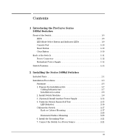
Contents 1 Introducing the ProCurve Series 5400zl Switches Front of the Switch 1-5 LEDs 1-6 LED Mode Select Button and Indicator LEDs 1-9 Console Port 1-10 Reset Button 1-10 Clear Button 1-10 Back of the Switch 1-11 Power Connector 1-12 Redundant Power Supply 1-12 Switch Features 1-13 2 Installing the Series 5400zl Switches Included Parts 2-1 Installation Procedures 2-3 Summary 2-3 1. Prepare the Installation Site 2-7 Cabling Infrastructure 2-7 Installation Location 2-8 2. Install Switch Modules 2-9 3. (Optional) Install Another Power Supply 2-12 4. Verify the Switch Passes Self Test 2-15 LED Behavior 2-16 5.Mount the Switch 2-17 Rack or Cabinet Mounting 2-17 2-20 Horizontal Surface Mounting 2-20 6. Install the Grounding Wire 2-21 7. Connect the Switch to a Power Source 2-21 iii

  • 1
  • 2
  • 3
  • 4
  • 5
  • 6
  • 7
  • 8
  • 9
  • 10
  • 11
  • 12
  • 13
  • 14
  • 15
  • 16
  • 17
  • 18
  • 19
  • 20
  • 21
  • 22
  • 23
  • 24
  • 25
  • 26
  • 27
  • 28
  • 29
  • 30
  • 31
  • 32
  • 33
  • 34
  • 35
  • 36
  • 37
  • 38
  • 39
  • 40
  • 41
  • 42
  • 43
  • 44
  • 45
  • 46
  • 47
  • 48
  • 49
  • 50
  • 51
  • 52
  • 53
  • 54
  • 55
  • 56
  • 57
  • 58
  • 59
  • 60
  • 61
  • 62
  • 63
  • 64
  • 65
  • 66
  • 67
  • 68
  • 69
  • 70
  • 71
  • 72
  • 73
  • 74
  • 75
  • 76
  • 77
  • 78
  • 79
  • 80
  • 81
  • 82
  • 83
  • 84
  • 85
  • 86
  • 87
  • 88
  • 89
  • 90
  • 91
  • 92
  • 93
  • 94
  • 95
  • 96
  • 97
  • 98
  • 99
  • 100
  • 101
  • 102
  • 103
  • 104
  • 105
  • 106
  • 107
  • 108
  • 109
  • 110
  • 111
  • 112
  • 113
  • 114
  • 115
  • 116
  • 117
  • 118

iii
Contents
1
Introducing the ProCurve Series
5400zl Switches
Front of the Switch . . . . . . . . . . . . . . . . . . . . . . . . . . . . . . . . . . . . . . . . . . . . . . 1-5
LEDs
. . . . . . . . . . . . . . . . . . . . . . . . . . . . . . . . . . . . . . . . . . . . . . . . . . . . . . 1-6
LED Mode Select Button and Indicator LEDs . . . . . . . . . . . . . . . . . . . . 1-9
Console Port
. . . . . . . . . . . . . . . . . . . . . . . . . . . . . . . . . . . . . . . . . . . . . . 1-10
Reset Button
. . . . . . . . . . . . . . . . . . . . . . . . . . . . . . . . . . . . . . . . . . . . . . 1-10
Clear Button . . . . . . . . . . . . . . . . . . . . . . . . . . . . . . . . . . . . . . . . . . . . . . . 1-10
Back of the Switch . . . . . . . . . . . . . . . . . . . . . . . . . . . . . . . . . . . . . . . . . . . . . 1-11
Power Connector
. . . . . . . . . . . . . . . . . . . . . . . . . . . . . . . . . . . . . . . . . . 1-12
Redundant Power Supply . . . . . . . . . . . . . . . . . . . . . . . . . . . . . . . . . . . . 1-12
Switch Features
. . . . . . . . . . . . . . . . . . . . . . . . . . . . . . . . . . . . . . . . . . . . . . . 1-13
2
Installing the Series 5400zl Switches
Included Parts . . . . . . . . . . . . . . . . . . . . . . . . . . . . . . . . . . . . . . . . . . . . . . . . . . 2-1
Installation Procedures
. . . . . . . . . . . . . . . . . . . . . . . . . . . . . . . . . . . . . . . . . . 2-3
Summary . . . . . . . . . . . . . . . . . . . . . . . . . . . . . . . . . . . . . . . . . . . . . . . . . . . 2-3
1. Prepare the Installation Site
. . . . . . . . . . . . . . . . . . . . . . . . . . . . . . . . 2-7
Cabling Infrastructure . . . . . . . . . . . . . . . . . . . . . . . . . . . . . . . . . . . . 2-7
Installation Location
. . . . . . . . . . . . . . . . . . . . . . . . . . . . . . . . . . . . . 2-8
2. Install Switch Modules . . . . . . . . . . . . . . . . . . . . . . . . . . . . . . . . . . . . . 2-9
3. (Optional) Install Another Power Supply . . . . . . . . . . . . . . . . . . . . . 2-12
4. Verify the Switch Passes Self Test
. . . . . . . . . . . . . . . . . . . . . . . . . . 2-15
LED Behavior:
. . . . . . . . . . . . . . . . . . . . . . . . . . . . . . . . . . . . . . . . . 2-16
5.Mount the Switch . . . . . . . . . . . . . . . . . . . . . . . . . . . . . . . . . . . . . . . . . 2-17
Rack or Cabinet Mounting
. . . . . . . . . . . . . . . . . . . . . . . . . . . . . . . 2-17
. . . . . . . . . . . . . . . . . . . . . . . . . . . . . . . . . . . . . . . . . . . . . . . . . . . . . . 2-20
Horizontal Surface Mounting
. . . . . . . . . . . . . . . . . . . . . . . . . . . . . 2-20
6. Install the Grounding Wire . . . . . . . . . . . . . . . . . . . . . . . . . . . . . . . . . 2-21
7. Connect the Switch to a Power Source
. . . . . . . . . . . . . . . . . . . . . . 2-21