HP LaserJet 5p/mp Supplement - Page 23
HP LaserJet 5p/mp Manual
 |
View all HP LaserJet 5p/mp manuals
Add to My Manuals
Save this manual to your list of manuals |
Page 23 highlights
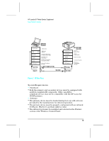
HP LaserJet 5P Printer Service Supplement New Product Features D C C o ntroller P C A PS 3 Figure 6 HP LaserJet 5P Printer Paper Path PS1 Input Paper Sensor PS2 Tray 2 Paper Out Sensor PS3 Exit Paper Sensor PS4 Winding Paper Sensor PS5 Tray 1 Paper Out Sensor Input Paper Sensor (PS1) Positions: A = Manual Feed Sense Position B = Registration Sense Position C = TOP Sense Position SL1 Tray 2 Solenoid SL2 Tray 1 Solenoid 17
-
 1
1 -
2
-
3
-
4
-
5
-
6
-
7
-
8
-
9
-
10
-
11
-
12
-
13
-
14
-
15
-
16
-
17
-
 18
18 -
 19
19 -
 20
20 -
 21
21 -
 22
22 -
 23
23 -
 24
24 -
 25
25 -
 26
26 -
 27
27 -
 28
28 -
29
-
30
-
31
-
32
-
33
-
34
-
35
-
36
-
37
-
38
-
39
-
40
-
41
-
42
-
43
-
44
-
45
-
46
-
47
-
48
-
49
-
50
-
51
-
52
-
53
-
54
-
55
-
56
-
57
-
58
-
59
-
60
-
61
-
62
-
63
-
64
-
65
-
66
-
67
-
68
-
69
-
70
-
71
-
72
-
73
-
74
-
75
-
76
-
77
-
78
-
79
-
80
-
81
-
82
-
83
-
84
-
85
-
86
-
87
-
88
-
89
-
90
-
91
-
92
-
93
-
94
-
95
-
96
-
97
 |
 |

PS
1
I
npu
t
P
ape
r
S
enso
r
I
npu
t
P
ape
r
S
enso
r
(
PS
1
)
P
os
i
t
i
ons
:
PS
2
T
r
ay
2
P
ape
r
O
u
t
S
enso
r
A
=
M
anua
l
F
eed
S
ense
P
os
i
t
i
on
PS
3
E
x
i
t
P
ape
r
S
enso
r
B
=
R
eg
i
s
t
r
a
t
i
on
S
ense
P
os
i
t
i
on
PS
4
W
i
nd
i
ng
P
ape
r
S
enso
r
C
=
TO
P
S
ense
P
os
i
t
i
on
PS
5
T
r
ay
1
P
ape
r
O
u
t
S
enso
r
S
L
1
T
r
ay
2
S
o
l
eno
i
d
S
L
2
T
r
ay
1
S
o
l
eno
i
d
DC Cont
r
o
ll
e
r
PCA
P
S
3
F
i
gu
r
e
6
HP
L
a
s
e
r
J
e
t 5
P
P
r
i
n
t
e
r
P
a
p
e
r
P
a
t
h
HP
Lase
r
J
e
t
5
P
P
r
i
n
t
e
r
S
e
r
v
i
ce
S
upp
l
e
m
en
t
N
e
w
P
r
oduc
t
F
ea
t
u
r
es
17