HP LaserJet 5p/mp Supplement - Page 53
Rr Sr
 |
View all HP LaserJet 5p/mp manuals
Add to My Manuals
Save this manual to your list of manuals |
Page 53 highlights
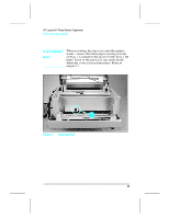
HP LaserJet 5P Printer Service Supplement Removal and Replacement Removing the Formatter Board and Shield 1. Remove any installed SIMMs. Note There are two TORX screws holding the I/O connector in position (Callout 1 in Figure 21). These are the only two TORX screws in the HP LaserJet 5P printer. Note also the location of the test print button hole (Callout 2) on the side of the formatter board cover. Figure 21 TORX Screw Locations. 47
-
 1
1 -
2
-
3
-
4
-
5
-
6
-
7
-
8
-
9
-
10
-
11
-
12
-
13
-
14
-
15
-
16
-
17
-
18
-
19
-
20
-
21
-
22
-
23
-
24
-
25
-
26
-
27
-
28
-
29
-
30
-
31
-
32
-
33
-
34
-
35
-
36
-
37
-
38
-
39
-
40
-
41
-
42
-
43
-
44
-
45
-
46
-
47
-
 48
48 -
 49
49 -
 50
50 -
 51
51 -
 52
52 -
 53
53 -
 54
54 -
 55
55 -
 56
56 -
 57
57 -
 58
58 -
59
-
60
-
61
-
62
-
63
-
64
-
65
-
66
-
67
-
68
-
69
-
70
-
71
-
72
-
73
-
74
-
75
-
76
-
77
-
78
-
79
-
80
-
81
-
82
-
83
-
84
-
85
-
86
-
87
-
88
-
89
-
90
-
91
-
92
-
93
-
94
-
95
-
96
-
97
 |
 |

R
e
mo
v
i
n
g
t
h
e
F
o
r
m
a
tt
e
r
B
o
a
r
d
a
n
d
S
h
i
e
l
d
1
.
R
e
m
o
v
e
a
n
y
i
n
s
t
a
ll
e
d
S
I
MM
s
.
N
o
t
e
T
h
e
r
e
a
r
e
t
w
o
T
O
R
X
s
c
r
e
w
s
h
o
l
d
i
n
g
t
h
e
I
/
O
co
nn
e
c
t
o
r
i
n
p
o
s
i
t
i
o
n
(
C
a
ll
o
u
t
1
i
n
F
i
g
u
r
e
21
)
.
T
h
e
s
e
a
r
e
t
h
e
o
n
l
y
t
w
o
T
O
R
X
s
c
r
e
w
s
i
n
t
h
e
H
P
L
a
s
e
r
J
e
t
5
P
p
r
i
n
t
e
r
.
N
o
t
e
a
l
s
o
t
h
e
l
oc
a
t
i
o
n
of
t
h
e
t
e
s
t
p
r
i
n
t
b
u
tt
o
n
h
o
l
e
(
C
a
ll
o
u
t
2
)
o
n
t
h
e
s
i
d
e
of
t
h
e
fo
r
m
a
tt
e
r
b
o
a
r
d
co
v
e
r
.
F
i
gu
r
e
21
T
O
R
X
S
c
r
e
w
L
o
ca
t
i
ons
.
HP
Lase
r
J
e
t
5
P
P
r
i
n
t
e
r
S
e
r
v
i
ce
S
upp
l
e
m
en
t
R
e
m
ova
l
and
R
ep
l
ace
m
en
t
47