HP Nw9440 HP Compaq nx9420 and nx9440 Notebook PC - Maintenance and Service Gu - Page 119
Remove the Torx8 T8M2.5×9.0 screw, the two Phillips PM2.0×4.0 screws
 |
UPC - 882780782174
View all HP Nw9440 manuals
Add to My Manuals
Save this manual to your list of manuals |
Page 119 highlights
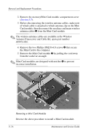
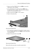
Removal and Replacement Procedures 3. Remove the Torx8 T8M2.5×9.0 screw 1 that secures the optical drive to the computer. 4. Use a flat-bladed tool to push the metal tab 2 toward the right side of the computer. (The optical drive partially removes from the optical drive bay.) 5. Slide the optical drive 3 out of the computer. 6. Remove the optical drive. Removing the Optical Drive 7. If it is necessary to replace the optical drive bracket, remove the two Phillips PM2.0×4.0 screws 1 that secure the bracket to the optical drive. 8. Remove the optical drive bracket 2. Removing the Optical Drive Reverse the above procedure to install an optical drive. Maintenance and Service Guide 5-19
-
 1
1 -
2
-
3
-
4
-
5
-
6
-
7
-
8
-
9
-
10
-
11
-
12
-
13
-
14
-
15
-
16
-
17
-
18
-
19
-
20
-
21
-
22
-
23
-
24
-
25
-
26
-
27
-
28
-
29
-
30
-
31
-
32
-
33
-
34
-
35
-
36
-
37
-
38
-
39
-
40
-
41
-
42
-
43
-
44
-
45
-
46
-
47
-
48
-
49
-
50
-
51
-
52
-
53
-
54
-
55
-
56
-
57
-
58
-
59
-
60
-
61
-
62
-
63
-
64
-
65
-
66
-
67
-
68
-
69
-
70
-
71
-
72
-
73
-
74
-
75
-
76
-
77
-
78
-
79
-
80
-
81
-
82
-
83
-
84
-
85
-
86
-
87
-
88
-
89
-
90
-
91
-
92
-
93
-
94
-
95
-
96
-
97
-
98
-
99
-
100
-
101
-
102
-
103
-
104
-
105
-
106
-
107
-
108
-
109
-
110
-
111
-
112
-
113
-
 114
114 -
 115
115 -
 116
116 -
 117
117 -
 118
118 -
 119
119 -
 120
120 -
 121
121 -
 122
122 -
 123
123 -
 124
124 -
125
-
126
-
127
-
128
-
129
-
130
-
131
-
132
-
133
-
134
-
135
-
136
-
137
-
138
-
139
-
140
-
141
-
142
-
143
-
144
-
145
-
146
-
147
-
148
-
149
-
150
-
151
-
152
-
153
-
154
-
155
-
156
-
157
-
158
-
159
-
160
-
161
-
162
-
163
-
164
-
165
-
166
-
167
-
168
-
169
-
170
-
171
-
172
-
173
-
174
-
175
-
176
-
177
-
178
-
179
-
180
-
181
-
182
-
183
-
184
-
185
-
186
-
187
-
188
-
189
-
190
-
191
-
192
-
193
-
194
-
195
-
196
-
197
-
198
-
199
-
200
-
201
-
202
-
203
-
204
-
205
-
206
-
207
-
208
-
209
-
210
-
211
-
212
-
213
-
214
-
215
-
216
-
217
-
218
-
219
-
220
-
221
-
222
-
223
-
224
-
225
-
226
-
227
-
228
-
229
-
230
-
231
-
232
-
233
-
234
-
235
-
236
-
237
-
238
-
239
-
240
-
241
-
242
-
243
-
244
-
245
-
246
-
247
-
248
-
249
-
250
-
251
-
252
-
253
-
254
-
255
-
256
-
257
-
258
-
259
-
260
-
261
-
262
-
263
-
264
-
265
-
266
 |
 |

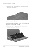
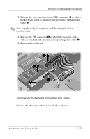
Removal and Replacement Procedures
Maintenance and Service Guide
5–19
3. Remove the Torx8 T8M2.5×9.0 screw
1
that secures the
optical drive to the computer.
4. Use a flat-bladed tool to push the metal tab
2
toward
the right side of the computer. (The optical drive partially
removes from the optical drive bay.)
5. Slide the optical drive
3
out of the computer.
6. Remove the optical drive.
Removing the Optical Drive
7. If it is necessary to replace the optical drive bracket, remove
the two Phillips PM2.0×4.0 screws
1
that secure the bracket
to the optical drive.
8. Remove the optical drive bracket
2
.
Removing the Optical Drive
Reverse the above procedure to install an optical drive.