HP Nw9440 HP Compaq nx9420 and nx9440 Notebook PC - Maintenance and Service Gu - Page 144
Video Board, Video Board Spare Part Number Information
 |
UPC - 882780782174
View all HP Nw9440 manuals
Add to My Manuals
Save this manual to your list of manuals |
Page 144 highlights
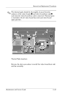
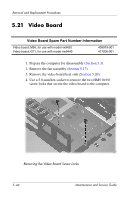
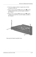
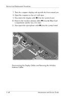
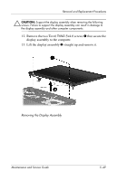
Removal and Replacement Procedures 5.21 Video Board Video Board Spare Part Number Information Video board, M56, for use with model nx9420 Video board, G71, for use with model nw9440 409979-001 417206-001 1. Prepare the computer for disassembly (Section 5.3). 2. Remove the fan assembly (Section 5.17). 3. Remove the video board heat sink (Section 5.20). 4. Use a 5.0-mm hex socket to remove the two HM5.0×9.0 screw locks that secure the video board to the computer. Removing the Video Board Screw Locks 5-44 Maintenance and Service Guide
-
 1
1 -
2
-
3
-
4
-
5
-
6
-
7
-
8
-
9
-
10
-
11
-
12
-
13
-
14
-
15
-
16
-
17
-
18
-
19
-
20
-
21
-
22
-
23
-
24
-
25
-
26
-
27
-
28
-
29
-
30
-
31
-
32
-
33
-
34
-
35
-
36
-
37
-
38
-
39
-
40
-
41
-
42
-
43
-
44
-
45
-
46
-
47
-
48
-
49
-
50
-
51
-
52
-
53
-
54
-
55
-
56
-
57
-
58
-
59
-
60
-
61
-
62
-
63
-
64
-
65
-
66
-
67
-
68
-
69
-
70
-
71
-
72
-
73
-
74
-
75
-
76
-
77
-
78
-
79
-
80
-
81
-
82
-
83
-
84
-
85
-
86
-
87
-
88
-
89
-
90
-
91
-
92
-
93
-
94
-
95
-
96
-
97
-
98
-
99
-
100
-
101
-
102
-
103
-
104
-
105
-
106
-
107
-
108
-
109
-
110
-
111
-
112
-
113
-
114
-
115
-
116
-
117
-
118
-
119
-
120
-
121
-
122
-
123
-
124
-
125
-
126
-
127
-
128
-
129
-
130
-
131
-
132
-
133
-
134
-
135
-
136
-
137
-
138
-
 139
139 -
 140
140 -
 141
141 -
 142
142 -
 143
143 -
 144
144 -
 145
145 -
 146
146 -
 147
147 -
 148
148 -
 149
149 -
150
-
151
-
152
-
153
-
154
-
155
-
156
-
157
-
158
-
159
-
160
-
161
-
162
-
163
-
164
-
165
-
166
-
167
-
168
-
169
-
170
-
171
-
172
-
173
-
174
-
175
-
176
-
177
-
178
-
179
-
180
-
181
-
182
-
183
-
184
-
185
-
186
-
187
-
188
-
189
-
190
-
191
-
192
-
193
-
194
-
195
-
196
-
197
-
198
-
199
-
200
-
201
-
202
-
203
-
204
-
205
-
206
-
207
-
208
-
209
-
210
-
211
-
212
-
213
-
214
-
215
-
216
-
217
-
218
-
219
-
220
-
221
-
222
-
223
-
224
-
225
-
226
-
227
-
228
-
229
-
230
-
231
-
232
-
233
-
234
-
235
-
236
-
237
-
238
-
239
-
240
-
241
-
242
-
243
-
244
-
245
-
246
-
247
-
248
-
249
-
250
-
251
-
252
-
253
-
254
-
255
-
256
-
257
-
258
-
259
-
260
-
261
-
262
-
263
-
264
-
265
-
266
 |
 |

5–44
Maintenance and Service Guide
Removal and Replacement Procedures
5.21
Video Board
1. Prepare the computer for disassembly (
Section 5.3
).
2. Remove the fan assembly (
Section 5.17
).
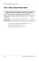
3. Remove the video board heat sink (
Section 5.20
).
4. Use a 5.0-mm hex socket to remove the two HM5.0×9.0
screw locks that secure the video board to the computer.
Removing the Video Board Screw Locks
Video Board Spare Part Number Information
Video board, M56, for use with model nx9420
Video board, G71, for use with model nw9440
409979-001
417206-001