HP Pavilion zd8000 HP Pavilion zd8000 Notebook PC - Maintenance and Service Gu - Page 106
Top Cover
 |
View all HP Pavilion zd8000 manuals
Add to My Manuals
Save this manual to your list of manuals |
Page 106 highlights
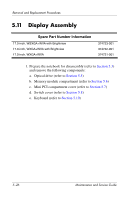
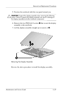
Removal and Replacement Procedures 5.12 Top Cover Spare Part Number Information Top cover (includes TouchPad) 374750-001 1. Prepare the notebook for disassembly (refer to Section 5.3) and remove the following components: a. Optical drive (refer to Section 5.5) b. Memory module compartment (refer to Section 5.6) c. Mini PCI compartment cover (refer to Section 5.7) d. Switch cover (refer to Section 5.8) e. Keyboard (refer to Section 5.10) f. Display assembly (refer to Section 5.11) 2. Turn the notebook upside down with the rear panel toward you. 5-30 Maintenance and Service Guide
-
 1
1 -
2
-
3
-
4
-
5
-
6
-
7
-
8
-
9
-
10
-
11
-
12
-
13
-
14
-
15
-
16
-
17
-
18
-
19
-
20
-
21
-
22
-
23
-
24
-
25
-
26
-
27
-
28
-
29
-
30
-
31
-
32
-
33
-
34
-
35
-
36
-
37
-
38
-
39
-
40
-
41
-
42
-
43
-
44
-
45
-
46
-
47
-
48
-
49
-
50
-
51
-
52
-
53
-
54
-
55
-
56
-
57
-
58
-
59
-
60
-
61
-
62
-
63
-
64
-
65
-
66
-
67
-
68
-
69
-
70
-
71
-
72
-
73
-
74
-
75
-
76
-
77
-
78
-
79
-
80
-
81
-
82
-
83
-
84
-
85
-
86
-
87
-
88
-
89
-
90
-
91
-
92
-
93
-
94
-
95
-
96
-
97
-
98
-
99
-
100
-
 101
101 -
 102
102 -
 103
103 -
 104
104 -
 105
105 -
 106
106 -
 107
107 -
 108
108 -
 109
109 -
 110
110 -
 111
111 -
112
-
113
-
114
-
115
-
116
-
117
-
118
-
119
-
120
-
121
-
122
-
123
-
124
-
125
-
126
-
127
-
128
-
129
-
130
-
131
-
132
-
133
-
134
-
135
-
136
-
137
-
138
-
139
-
140
-
141
-
142
-
143
-
144
-
145
-
146
-
147
-
148
-
149
-
150
-
151
-
152
-
153
-
154
-
155
-
156
-
157
-
158
-
159
-
160
-
161
-
162
-
163
-
164
-
165
-
166
-
167
-
168
-
169
-
170
-
171
-
172
-
173
-
174
-
175
-
176
-
177
-
178
-
179
-
180
-
181
-
182
-
183
-
184
-
185
-
186
-
187
-
188
-
189
 |
 |

5–30
Maintenance and Service Guide
Removal and Replacement Procedures
5.12
Top Cover
1. Prepare the notebook for disassembly (refer to
Section 5.3
)
and remove the following components:
a.
Optical drive (refer to
Section 5.5
)
b.
Memory module compartment (refer to
Section 5.6
)
c.
Mini PCI compartment cover (refer to
Section 5.7
)
d.
Switch cover (refer to
Section 5.8
)
e.
Keyboard (refer to
Section 5.10
)
f.
Display assembly (refer to
Section 5.11
)
2. Turn the notebook upside down with the rear panel
toward you.
Spare Part Number Information
Top cover (includes TouchPad)
374750-001