HP Pavilion zd8000 HP Pavilion zd8000 Notebook PC - Maintenance and Service Gu - Page 131
between the heat sink module and processor, it may
 |
View all HP Pavilion zd8000 manuals
Add to My Manuals
Save this manual to your list of manuals |
Page 131 highlights
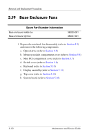
Removal and Replacement Procedures 2. Disconnect the fan cable from the system board 1. 3. According to the 1, 2, 3, 4 sequence stamped into the heat sink module, loosen the four PM2.0×12.0 spring-loaded shoulder screws 2 that secure the heat sink module to the system board. 4. Lift the heat sink module and remove it 3. ✎ Due to the adhesive quality of the thermal paste located between the heat sink module and processor, it may be necessary to move the module from side to side to detach the module from the processor. Removing the Heat Sink Module Reverse the above procedure to install the heat sink module. Maintenance and Service Guide 5-55
-
 1
1 -
2
-
3
-
4
-
5
-
6
-
7
-
8
-
9
-
10
-
11
-
12
-
13
-
14
-
15
-
16
-
17
-
18
-
19
-
20
-
21
-
22
-
23
-
24
-
25
-
26
-
27
-
28
-
29
-
30
-
31
-
32
-
33
-
34
-
35
-
36
-
37
-
38
-
39
-
40
-
41
-
42
-
43
-
44
-
45
-
46
-
47
-
48
-
49
-
50
-
51
-
52
-
53
-
54
-
55
-
56
-
57
-
58
-
59
-
60
-
61
-
62
-
63
-
64
-
65
-
66
-
67
-
68
-
69
-
70
-
71
-
72
-
73
-
74
-
75
-
76
-
77
-
78
-
79
-
80
-
81
-
82
-
83
-
84
-
85
-
86
-
87
-
88
-
89
-
90
-
91
-
92
-
93
-
94
-
95
-
96
-
97
-
98
-
99
-
100
-
101
-
102
-
103
-
104
-
105
-
106
-
107
-
108
-
109
-
110
-
111
-
112
-
113
-
114
-
115
-
116
-
117
-
118
-
119
-
120
-
121
-
122
-
123
-
124
-
125
-
 126
126 -
 127
127 -
 128
128 -
 129
129 -
 130
130 -
 131
131 -
 132
132 -
 133
133 -
 134
134 -
 135
135 -
 136
136 -
137
-
138
-
139
-
140
-
141
-
142
-
143
-
144
-
145
-
146
-
147
-
148
-
149
-
150
-
151
-
152
-
153
-
154
-
155
-
156
-
157
-
158
-
159
-
160
-
161
-
162
-
163
-
164
-
165
-
166
-
167
-
168
-
169
-
170
-
171
-
172
-
173
-
174
-
175
-
176
-
177
-
178
-
179
-
180
-
181
-
182
-
183
-
184
-
185
-
186
-
187
-
188
-
189
 |
 |

Removal and Replacement Procedures
Maintenance and Service Guide
5–55
2. Disconnect the fan cable from the system board
1
.
3. According to the 1, 2, 3, 4 sequence stamped into the heat
sink module, loosen the four PM2.0×12.0 spring-loaded
shoulder screws
2
that secure the heat sink module to the
system board.
4. Lift the heat sink module and remove it
3
.
✎
Due to the adhesive quality of the thermal paste located
between the heat sink module and processor, it may be
necessary to move the module from side to side to detach the
module from the processor.
Removing the Heat Sink Module
Reverse the above procedure to install the heat sink module.