HP Presario CQ20-100 Compaq Presario CQ20 Notebook PC - Maintenance and Servic - Page 48
Top cover, Optical drive see
 |
View all HP Presario CQ20-100 manuals
Add to My Manuals
Save this manual to your list of manuals |
Page 48 highlights
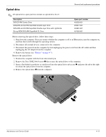
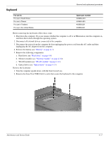
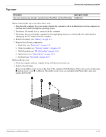
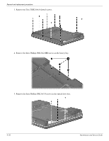
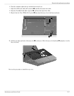
Top cover Removal and replacement procedures Description Spare part number Top cover (includes caps lock light, capacitive board, TouchPad, and TouchPad cable) 493962-001 Before removing the top cover, follow these steps: 1. Shut down the computer. If you are unsure whether the computer is off or in Hibernation, turn the computer on, and then shut it down through the operating system. 2. Disconnect all external devices connected to the computer. 3. Disconnect the power from the computer by first unplugging the power cord from the AC outlet and then unplugging the AC adapter from the computer. 4. Remove the battery (see "Battery" on page 4-7). 5. Remove the following components: a. Hard drive (see "Hard drive" on page 4-8) b. Memory module (see "Memory module" on page 4-10) c. WLAN module (see "WLAN module" on page 4-12) d. Optical drive (see "Optical drive" on page 4-15) e. Keyboard (see "Keyboard" on page 4-17) Remove the top cover: 1. Close the computer and turn it upside down, with the front toward you. 2. Remove the following: Remove four rubber screw covers on the front of the computer. Note that three of the screw covers are the same 1 and one screw cover 2 is different. The rubber screw covers are included in the Plastics Kit, spare part number 493274-001. Maintenance and Service Guide 4-19
-
 1
1 -
2
-
3
-
4
-
5
-
6
-
7
-
8
-
9
-
10
-
11
-
12
-
13
-
14
-
15
-
16
-
17
-
18
-
19
-
20
-
21
-
22
-
23
-
24
-
25
-
26
-
27
-
28
-
29
-
30
-
31
-
32
-
33
-
34
-
35
-
36
-
37
-
38
-
39
-
40
-
41
-
42
-
 43
43 -
 44
44 -
 45
45 -
 46
46 -
 47
47 -
 48
48 -
 49
49 -
 50
50 -
 51
51 -
 52
52 -
 53
53 -
54
-
55
-
56
-
57
-
58
-
59
-
60
-
61
-
62
-
63
-
64
-
65
-
66
-
67
-
68
-
69
-
70
-
71
-
72
-
73
-
74
-
75
-
76
-
77
-
78
-
79
-
80
-
81
-
82
-
83
-
84
-
85
-
86
-
87
-
88
-
89
-
90
-
91
-
92
-
93
-
94
-
95
-
96
-
97
-
98
-
99
-
100
-
101
-
102
-
103
-
104
-
105
-
106
-
107
-
108
-
109
-
110
-
111
-
112
-
113
-
114
-
115
-
116
-
117
-
118
-
119
-
120
 |
 |