HP Tx2635us HP Pavilion tx2500 Entertainment PC - Maintenance and Service Guid - Page 56
away from the slot at an angle and remove it., Pull the WLAN module
 |
UPC - 884420449898
View all HP Tx2635us manuals
Add to My Manuals
Save this manual to your list of manuals |
Page 56 highlights
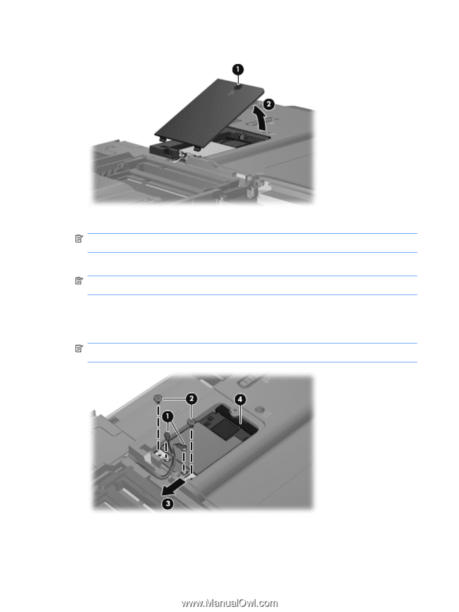
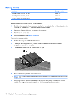
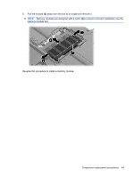
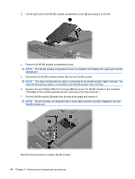
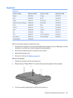
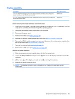
3. Lift the right side of the WLAN module compartment cover (2) and swing it to the left. 4. Remove the WLAN module compartment cover. NOTE: The WLAN module compartment cover is included in the Plastics Kit, spare part number 487926-001. 5. Disconnect the WLAN antenna cables (1) from the WLAN module. NOTE: The black WLAN antenna cable is connected to the WLAN module "Main" terminal. The white WLAN antenna cable is connected to the WLAN module "Aux" terminal. 6. Remove the two Phillips PM2.0×3.0 screws (2) that secure the WLAN module to the computer. (The edge of the module opposite the slot rises away from the computer.) 7. Pull the WLAN module (3) away from the slot at an angle and remove it. NOTE: WLAN modules are designed with a notch (4) to prevent incorrect installation into the WLAN module slot. Reverse this procedure to install a WLAN module. 48 Chapter 4 Removal and replacement procedures
-
 1
1 -
2
-
3
-
4
-
5
-
6
-
7
-
8
-
9
-
10
-
11
-
12
-
13
-
14
-
15
-
16
-
17
-
18
-
19
-
20
-
21
-
22
-
23
-
24
-
25
-
26
-
27
-
28
-
29
-
30
-
31
-
32
-
33
-
34
-
35
-
36
-
37
-
38
-
39
-
40
-
41
-
42
-
43
-
44
-
45
-
46
-
47
-
48
-
49
-
50
-
 51
51 -
 52
52 -
 53
53 -
 54
54 -
 55
55 -
 56
56 -
 57
57 -
 58
58 -
 59
59 -
 60
60 -
 61
61 -
62
-
63
-
64
-
65
-
66
-
67
-
68
-
69
-
70
-
71
-
72
-
73
-
74
-
75
-
76
-
77
-
78
-
79
-
80
-
81
-
82
-
83
-
84
-
85
-
86
-
87
-
88
-
89
-
90
-
91
-
92
-
93
-
94
-
95
-
96
-
97
-
98
-
99
-
100
-
101
-
102
-
103
-
104
-
105
-
106
-
107
-
108
-
109
-
110
-
111
-
112
-
113
-
114
-
115
-
116
-
117
-
118
-
119
-
120
-
121
-
122
-
123
-
124
-
125
 |
 |