HP Tx2635us HP Pavilion tx2500 Entertainment PC - Maintenance and Service Guid - Page 61
Display assembly, Close the computer and turn it upside down, with the front toward you.
 |
UPC - 884420449898
View all HP Tx2635us manuals
Add to My Manuals
Save this manual to your list of manuals |
Page 61 highlights
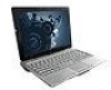
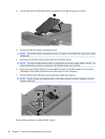
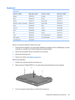
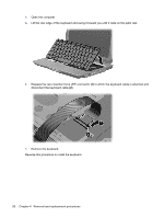
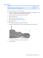
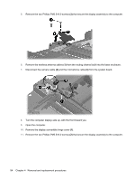
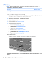
Display assembly Description Spare part number 12.1-inch, WXGA, BrightView touch-screen display assembly with Web camera, fingerprint reader, microphones, and WLAN antenna cables 484751-001 12.1-inch, WXGA, BrightView touch-screen display assembly with Web camera, microphones, 484750-001 and WLAN antenna cables Before removing the display assembly, follow these steps: 1. Shut down the computer. If you are unsure whether the computer is off or in Hibernation, turn the computer on, and then shut it down through the operating system. 2. Disconnect all external devices connected to the computer. 3. Disconnect the power cord. 4. Remove the battery (see Battery on page 39). 5. Remove the memory module compartment cover (see Memory module on page 44). 6. Remove the WLAN module compartment cover and disconnect the wireless antenna cables from the WLAN module (see WLAN module on page 46). 7. Remove the keyboard (see Keyboard on page 49). 8. Remove the switch cover (see Switch cover on page 51). Remove the display assembly: 1. Close the computer and turn it upside down, with the front toward you. 2. Loosen the Phillips PM2.0×5.0 captive screw (1) that secures the display connector cover to the computer. 3. Lift the rear edge of the display connector cover (2) and swing it toward you. 4. Remove the display connector cover. NOTE: The display connector cover is included in the Plastics Kit, spare part number 487926-001. Component replacement procedures 53
-
 1
1 -
2
-
3
-
4
-
5
-
6
-
7
-
8
-
9
-
10
-
11
-
12
-
13
-
14
-
15
-
16
-
17
-
18
-
19
-
20
-
21
-
22
-
23
-
24
-
25
-
26
-
27
-
28
-
29
-
30
-
31
-
32
-
33
-
34
-
35
-
36
-
37
-
38
-
39
-
40
-
41
-
42
-
43
-
44
-
45
-
46
-
47
-
48
-
49
-
50
-
51
-
52
-
53
-
54
-
55
-
 56
56 -
 57
57 -
 58
58 -
 59
59 -
 60
60 -
 61
61 -
 62
62 -
 63
63 -
 64
64 -
 65
65 -
 66
66 -
67
-
68
-
69
-
70
-
71
-
72
-
73
-
74
-
75
-
76
-
77
-
78
-
79
-
80
-
81
-
82
-
83
-
84
-
85
-
86
-
87
-
88
-
89
-
90
-
91
-
92
-
93
-
94
-
95
-
96
-
97
-
98
-
99
-
100
-
101
-
102
-
103
-
104
-
105
-
106
-
107
-
108
-
109
-
110
-
111
-
112
-
113
-
114
-
115
-
116
-
117
-
118
-
119
-
120
-
121
-
122
-
123
-
124
-
125
 |
 |